In environmental reliability testing, temperature test chambers and thermal shock test chambers are two core instruments designed to verify the performance stability of products under extreme temperature conditions. However, they differ significantly in temperature change mode, test objectives, core parameters, and application scenarios.
As a national high-tech enterprise with over 20 years of industry experience, Lab Companion. leverages mature R&D and manufacturing capabilities to provide comprehensive environmental testing solutions across multiple industries. This article compares the two types of chambers from three dimensions: core parameters, structural design, and application scenarios, and offers targeted selection advice based on Lab Companion’s product features to help enterprises select the optimal testing equipment.
1. Core Performance Parameters: Fundamental Difference Between Gradual & Sudden Temperature Change
The core distinction between the two instruments lies in their design positioning for temperature change modes:
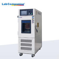
• Temperature Test Chamber: Gradual temperature change, steady-state constant temperature
• Thermal Shock Test Chamber: Sudden temperature shock, rapid switching
1.1 Temperature Range & Temperature Change Rate
Temperature Test Chamber
• Temperature range: Standard -70℃ ~ 150℃; customizable up to -100℃ ~ 200℃
• Temperature change feature: Average gradual rate; standard heating ≈ 5℃/min, cooling ≈ 3℃/min
• Rapid temperature change model: Equipped with dual-stage compression + eco-friendly refrigerant, with a rate of up to 20℃/min, suitable for accelerated aging tests
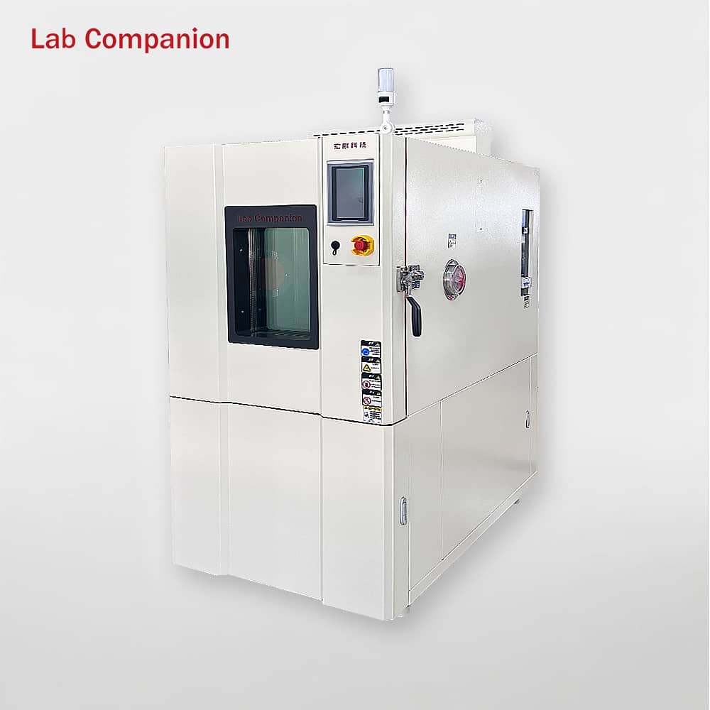
Lab Companion Thermal Shock Test Chamber (TS Series)
• Temperature range: Standard -65℃ ~ 150℃; customizable to -80℃ ~ 200℃
• Core advantage: Instant temperature switching (instead of average rate)
• Two-zone (TS2): Temperature transfer time ≤ 30 seconds, ≤ 10 seconds for small samples
• Three-zone (TS3): Equipped with pre-heating & pre-cooling chamber design, featuring higher switching efficiency and more stable shock performance
1.2 Temperature Uniformity & Fluctuation
Temperature Test Chamber
• Focuses on the accuracy of steady-state temperature field
• No-load uniformity ≤ ±2℃ (up to ±1.5℃)
• Fluctuation ≤ ±0.5℃; precision model up to ±0.3℃
• Ideal for long-term constant temperature and cyclic gradual change tests
Thermal Shock Test Chamber
• Slightly wider stability tolerance due to frequent temperature switching
• Uniformity ≤ ±1.5℃
• Fluctuation: Three-zone ≤ ±0.3℃, Two-zone ≤ ±0.5℃
• Equipped with dedicated PID algorithm for dynamic temperature control, reducing overshoot and ensuring consistent shock accuracy
1.3 Core Parameter Comparison (Compact Version)
Parameter
Temperature Test Chamber
Thermal Shock Test Chamber (TS Series)
Temperature Range
Standard: -70℃ ~ 150℃;Custom: -100℃ ~ 200℃
Standard: -65℃ ~ 150℃;Custom: -80℃ ~ 200℃
Temperature Change
Gradual change, average 0.5~20℃/min
Sudden thermal shock, transfer ≤ 30s, recovery ≤ 5min
Uniformity / Fluctuation
Uniformity ≤ ±2℃ (±1.5℃), Fluctuation ≤ ±0.5℃
Uniformity ≤ ±1.5℃, Fluctuation ±0.3~±0.5℃
Cycle Programming
1~999 programmable cycles, multi-segment curves
1~999 adjustable cycles, supports continuous shock
2. Structural & System Design: Differentiated Architectures for Diverse Temperature Change Needs
2.1 Refrigeration System
Temperature Test Chamber
• Above -40℃: Single-stage compression refrigeration
• Low-temperature range: Dual-stage cascade system with imported brand compressors
• Full-capillary automatic load regulation, ensuring precise temperature control and over 30% lower energy consumption
Thermal Shock Test Chamber (TS Series)
• Binary cascade air-cooled refrigeration system (high-temperature + low-temperature circuits)
• Adopts eco-friendly refrigerants R23/R404A, compliant with environmental protection regulations
• Mean Time Between Failures (MTBF) > 8,000 hours
2.2 Chamber & Air Duct Design
Temperature Test Chamber
• Single-chamber structure, inner tank made of SUS304 mirror stainless steel
• High-density polyurethane foam + silicone rubber seal, achieving superior thermal insulation performance
• 3D circulating air duct (top supply, bottom return), ensuring uniform temperature field and high versatility
Thermal Shock Test Chamber
• Two-zone (TS2): Equipped with pneumatic basket for direct sample transfer between hot and cold chambers; compact structure and cost-effective
• Three-zone (TS3): Additional intermediate transition chamber to reduce hot-cold air interference, lower temperature loss and improve precision – ideal for precision samples
• Inner tank: SUS304 stainless steel; outer cabinet: anti-corrosion electrolytic plate with paint finish
2.3 Control System
Temperature Test Chamber
• Siemens PLC + 7-inch touchscreen
• 100+ programs storage, 99 segments per program
• Segmented PID + AI adaptive control, with 99.5% data repeatability
Thermal Shock Test Chamber
• Youyi E-560/600 or 7.5-inch color touchscreen
• 96 program storage slots, embedded PLC for dynamic load adaptation
• Standard RS-232/RS485 interface, supporting data export and remote monitoring
3. Test Functions & Application Scenarios: Precise Matching for Industry Testing Needs
3.1 Temperature Test Chamber: General-Purpose Gradual Temperature Change Testing
Core Purpose
Simulate gradual temperature environments such as diurnal temperature variation and seasonal alternation; support constant temperature, high-low temperature cycling, and multi-segment programmable testing.
Applicable Industries
• Standard model: Consumer electronics, home appliances, plastics, hardware, and other general temperature resistance verification
• Rapid temperature change model: New energy, automotive electronics, 5G communications, aerospace, and other accelerated aging & cyclic reliability tests
• Customizable: Explosion-proof, anti-corrosion, large-volume, low-humidity, and other special working conditions
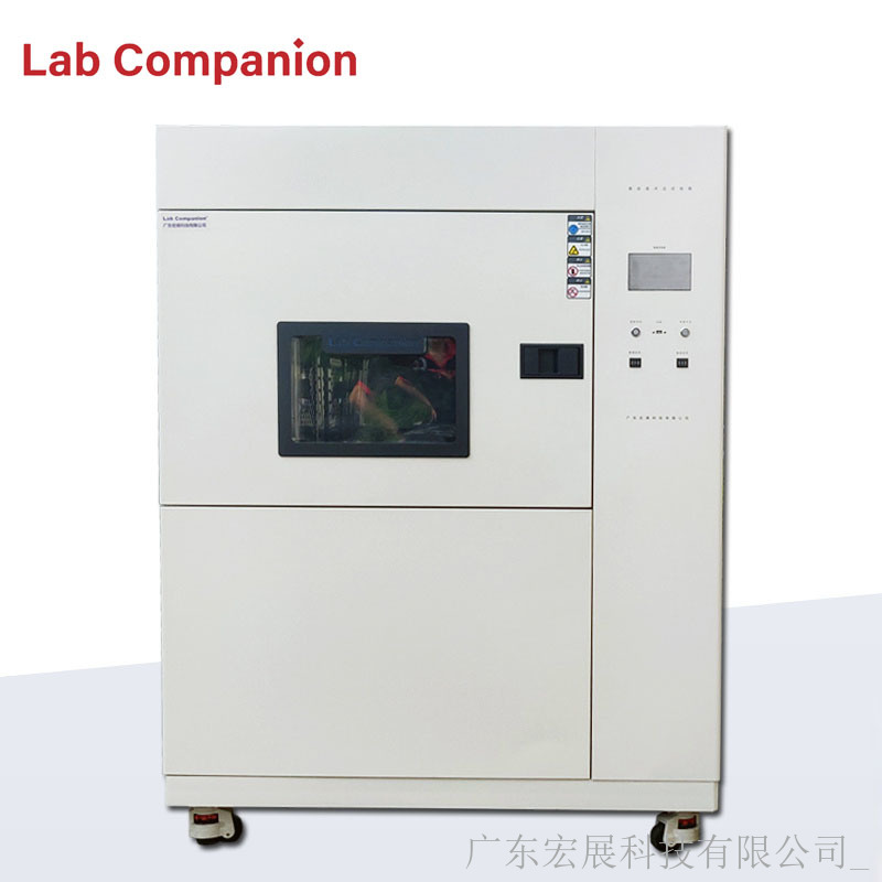
3.2 Thermal Shock Test Chamber: Severe Sudden Temperature Change Testing
Core Purpose
Simulate instantaneous extreme temperature changes during transportation or operation; evaluate cracking, failure, and performance drift caused by thermal expansion and contraction of materials.
Applicable Industries
• Aerospace: Instant temperature change between high altitude and ground
• Automotive components: Shock from cold start to high-temperature driving
• Harsh reliability verification for electronics, metals, rubber, military, and other fields
• Two-zone: Suitable for scenarios with limited budget and general thermal shock requirements
• Three-zone: Suitable for high-standard requirements (ISO, GB/T, etc.) in precision electronics, military, and other fields
4. Core Selection Logic & Precautions
Selection Priority: Demand Matching > Blind High Configuration
By Temperature Change Mode
• Gradual change & long-term steady state → Choose temperature test chamber
• Instant sudden change & thermal shock → Choose thermal shock test chamber
By Industry & Standards
• Consumer electronics, home appliances, basic materials → Temperature test chamber for better cost performance
• New energy, automotive, aerospace, military → Rapid temperature change chamber or three-zone thermal shock chamber
By Budget & Maintenance
• Temperature test chamber: Simple structure, low procurement and maintenance costs
• Thermal shock test chamber: Multi-chamber + cascade refrigeration, with slightly higher cost and maintenance requirements
Safety & After-Sales (Lab Companion Standard)
• 12 safety protection functions: Over-temperature, overload, compressor overheating, water shortage, fan failure, etc.
• National after-sales service network, providing regular maintenance guidance to ensure long-term stable operation
Conclusion
Temperature test chambers and thermal shock test chambers are not substitutes but complementary for different scenarios:
• Temperature Test Chamber: General-purpose, gradual change, steady state, cost-effective
• Thermal Shock Test Chamber: Severe, sudden change, shock-resistant, high-reliability verification
By combining product characteristics, industry standards, and test objectives with <span
The three core functions of high-low temperature test chambers—constant temperature, high-low temperature cycling, and programmable operation—extensively cover environmental reliability testing requirements across industries including electronics, automotive, military, photovoltaic, and more.
As a high-tech enterprise with over 20 years of expertise in environmental reliability testing equipment, Lab Companion specializes in the R&D and manufacturing of environmental test equipment. Its products feature precise temperature control and customizable capabilities to adapt to diverse industry applications.
Understanding the core operation, practical techniques, and selection logic of each function enables precise matching to different test scenarios, effectively improving test efficiency and data reliability. Based on Lab Companion’s mature product technologies and industry practical experience, we provide the following concise professional guide.
1. Constant Temperature Test: Basic Temperature Resistance Verification
Core Purpose
Used for long-term performance testing of products under a single extreme temperature condition. It is the most common basic test mode for mass quality inspection and preliminary R&D, with easy operation and strong versatility.
Typical Applications
- High-temperature aging test of semiconductor components at 85°C- Low-temperature embrittlement verification of automotive rubber seals at -40°C- Constant-temperature storage stability testing of in vitro diagnostic reagents for medical devices at 50°C
Key Operational Points
- Prioritize models with temperature fluctuation ≤ ±0.5°C and uniformity ≤ ±2°C; high-precision versions achieve ±0.1–±0.3°C.- Standardized sample placement: sample volume ≤ 1/3 of working chamber volume, distance from chamber walls ≥ 5 cm to avoid blocking air ducts and compromising temperature uniformity.
Product Features (Lab Companion)
- Inner chamber made of SUS304 mirror-finish stainless steel for corrosion resistance and easy cleaning.- High-density polyurethane foam insulation and high-strength heat-resistant silicone gaskets minimize heat exchange and enhance temperature stability.- Custom ultra-low temperature models below -100°C available for military applications, fully compliant with GJB military standards.
2. High-Low Temperature Cycling Test: Thermal Cycling Reliability Testing
Core Purpose
Simulates temperature alternating environments such as day-night temperature differences, regional transportation, and seasonal changes encountered in real-world use. It rigorously verifies structural strength and performance stability, with stricter evaluation than constant temperature testing.
Typical Applications
- Thermal cycling test of new energy vehicle power batteries from -30°C to 85°C (simulating winter-summer conditions)- High-low temperature cycling verification of photovoltaic modules- Wide-temperature-range alternating performance testing of aerospace composite materials
Key Operational Points
- Standard models: heating rate up to 5°C/min, cooling rate up to 3°C/min.- High-performance models: two-stage compression refrigeration + eco-friendly refrigerant, stable temperature change rate up to 20°C/min, greatly shortening test cycles.- Enable PID auto-tuning to limit temperature overshoot within 0.8°C for accurate data.
Product Features (Lab Companion)
- Equipped with Balanced Temperature Control (BTHC) system for precise execution of preset cycling programs, preventing damage from sudden temperature changes.- Full-capillary automatic load adjustment system delivers higher accuracy and stability than conventional expansion valves, while reducing energy consumption by more than 30%.
3. Programmable Test: Automated Simulation of Complex Working Conditions
Core Purpose
Supports multi-segment linked programming of temperature and time parameters, enabling fully automatic operation of complex test sequences without manual supervision. Ideal for customized R&D testing and standardized quality inspection.
Typical Applications
- Multi-region temperature environment simulation for 5G base station PCBs- 1000-hour long-term cyclic aging testing of electronic components- Multi-temperature gradient verification for military-grade products
Key Operational Points
- Select models supporting at least 100 program groups (expandable to 200), with up to 99 segments per program.- Set segmented PID parameters according to thermal inertia differences between high and low temperature ranges for improved full-range accuracy.
Product Features (Lab Companion)
- Siemens PLC control + 7-inch color touchscreen for intuitive and stable operation.- AI adaptive algorithm ensures test data repeatability up to 99.5%.- Supports USB, RS485, and Ethernet communication for remote monitoring and real-time data export.- Automatically generates GLP-compliant test reports; power-off memory function resumes testing automatically after power restoration to prevent data loss.
4. Selection & Operation Guidelines
1. Selection Logic
- Basic quality inspection: Choose constant temperature models for optimal cost-effectiveness.- Product reliability validation: Select cycling models; fast temperature change versions recommended for new energy and automotive industries.- R&D or complex conditions: Choose programmable models.- Military & aerospace: Custom options available for low pressure, explosion-proof, and other non-standard functions.
2. Safety & Maintenance
- Equipment must include multiple protections: over-temperature, overload, compressor overheating, etc.- Regularly clean air ducts, inspect door gaskets, and calibrate temperature sensors every 3–6 months to extend service life and maintain accuracy.
3. Customization Options
Optional accessories available based on industry needs: test ports, data loggers, explosion-proof chambers, water purification systems, etc., to meet special testing requirements in medical, chemical, military, and other fields.
Conclusion
The three core functions of high-low temperature test chambers provide complete testing coverage from basic verification to high-precision simulation. By selecting the appropriate function based on product characteristics, industry standards, and test requirements—paired with equipment featuring precise temperature control, stable performance, and customization—along with standardized operation and maintenance, users can maximize equipment value and provide reliable assurance for product quality.
In environmental simulation testing, temperature chambers’ control accuracy, rate stability and energy efficiency directly determine test data reliability and cost-effectiveness. With over 20 years of technical expertise, Labcompanion integrates dual PID temperature control and energy compensation into its chambers, breaking the traditional trade-off between accuracy and efficiency. It delivers high precision, fast response and low energy consumption, meeting stringent demands in automotive, semiconductor, military and other industries. This document analyzes the two core technologies from technical principles, collaborative advantages and application scenarios.
I. Dual PID Temperature Control: Core of Precise Temperature Regulation
Upgraded from traditional single PID, Labcompanion’s dual PID system integrates AI fuzzy algorithm to achieve intelligent adaptive control, with core advantages as follows:
• Dual-loop control: Takes temperature deviation and temperature change rate as input variables, dynamically optimizes PID parameters via fuzzy reasoning, and adapts to samples with different heat capacities without manual intervention.
• Temperature-humidity independence: Integrates water vapor partial pressure control to avoid coupling interference, with humidity fluctuation controlled at ±1%~±3%RH.
• Low-temperature performance: Independent closed-loop control by refrigerators reduces internal energy loss; temperature fluctuation stabilizes at ±0.1~±0.5℃, 30% more accurate than traditional equipment.
• Rate & program compatibility: 0.1℃/min~20℃/min full-range rate (20℃/min under load for T-200-20 model); built-in standard program templates, supports 200+ custom programs, compatible with GB/T, GJB, JEDEC standards.
II. Energy Compensation: Guarantee for Efficiency & Stability
Labcompanion’s energy compensation technology addresses energy loss and temperature zone crosstalk through hardware-software synergy, with key advantages as follows:
• Hardware optimization: Equipped with inverter compressors, binary refrigeration system and plate heat exchangers to adjust cooling/heating power dynamically; energy storage design for high-low temperature switching reduces energy consumption; 3-second pneumatic dampers control energy crosstalk within ±1℃ for three-chamber models.
• Intelligent energy adjustment: Deeply linked with dual PID + AI algorithm, adjusts compensation strategies in real time; energy consumption during constant temperature is reduced by over 40%.
• Green compliance: Binary cascade refrigerant configuration (R404A for high-temperature cycle, R23 for low-temperature cycle) meets dual-carbon goals.
III. Synergistic Advantages of Dual Technologies
• Maintains ±0.5℃ deviation and ≤±2℃ uniformity even at 20℃/min high-speed temperature change (under load), avoiding sample damage.
• Balances energy consumption and stability, reducing fault shutdown rate for long-term cycle tests.
• Covers -70℃~180℃ conventional temperature range (extendable for customized models), adapting to diverse test needs.
• Modular design: Two-chamber models for batch screening (basket moving time ≤10s); three-chamber models for precision power-on tests.
IV. Industry Applications
• Automotive components: Simulates -40℃~125℃ driving cycle temperature changes, compatible with condensation tests and ISO 16750-4 standard.
• Semiconductor & automotive electronics: 150L~1000L full-spec models for small-batch tests; ±0.1~±0.3℃ control accuracy meets JEDEC standards, exposing chip defects.
• Military: Complies with GJB 150.3A/GJB 150.4A standards; supports high-voltage explosion-proof and ultra-low temperature (-220℃ standard for customized models) configurations, serving aerospace and military equipment testing.
V. Summary
Dual PID temperature control ensures precision, while energy compensation achieves energy saving. Together, they realize three-dimensional optimization of precision, efficiency and energy consumption. Labcompanion provides customized solutions for various industries, supporting laboratory intelligence and green upgrading, and helping enterprises improve product reliability and reduce test costs.
The core function of cooling in a test chamber is to dissipate heat and regulate temperature, ensuring stable operation of key components such as the compressor. The two common cooling methods are air cooling and water cooling , which differ significantly in heat transfer medium, application scenarios, advantages, and limitations. A detailed analysis is provided below.
I. Air Cooling
1. Core Principle
Heat is dissipated through air circulation. Fans drive ambient air flow to remove heat generated by the compressor and refrigeration system, using air directly as the cooling medium without additional media.
2.Application Conditions
Optimal cooling efficiency is achieved when the ambient operating temperature is maintained at “25±5℃”, the range where air heat exchange efficiency peaks.
3.Key Advantages
l Low maintenance cost & convenience: No auxiliary equipment required; only regular cleaning of fans and filters is needed, with no piping or cooling tower maintenance.
l Suitable for northern China climates: Northern regions have consistently low temperatures, easily meeting the 25±5℃ requirement for stable heat dissipation, making it the mainstream choice.
l Flexible installation: No complex piping; plug-and-use operation with no obstacles to relocation or site adjustment.
4.Main Disadvantages
l Highly ambient temperature-dependent: In high ambient temperatures (e.g., summer heat, enclosed spaces), air heat exchange efficiency drops sharply, severely reducing cooling performance.
l Impacts equipment lifespan: Compressors operate under high load in high temperatures, shortening service life with prolonged use.
l Slow cooling speed: Air has low specific heat capacity, resulting in lower heat transfer efficiency than water and slower cooling under identical conditions.
II. Water Cooling
1. Core Principle
Water serves as the cooling medium, leveraging its fluidity and high specific heat capacity. Circulating water absorbs heat from the refrigeration system, which is then released via external devices (cooling tower, chiller) for continuous heat dissipation.
2.Supporting Requirements
Requires additional installation of a cooling tower, water pump, dedicated circulation piping, or integration with a standalone chiller to form a complete water circulation cooling system.
3.Key Advantages
l Ambient temperature-independent : Stable heat dissipation regardless of high temperatures or enclosed spaces, with strong adaptability.
l High heat dissipation efficiency & fast cooling : Water’s far higher specific heat capacity enables rapid heat transfer and temperature reduction.
l Extended equipment lifespan : Compressors run efficiently under low load, significantly prolonging service life.
l Suitable for southern China climates : Southern regions experience hot, humid summers where air cooling is easily compromised, making water cooling the preferred option.
4.Main Disadvantages
l High upfront investment : Additional costs for purchasing cooling towers, pumps, pipes, and related installation and materials.
l Complex installation & relocation : Piping layout requires advance planning; fixed sites are difficult to relocate or modify.
l Ongoing maintenance needs : Regular water quality checks and pipe scale removal are necessary to prevent clogging and maintain circulation efficiency.
III. Core Summary of Air Cooling vs. Water Cooling
l Identical core purpose : Both methods cool test chambers by dissipating heat, differing only in cooling medium (air/water) and heat transfer path.
l No absolute superiority : Selection depends primarily on test site environment, climate conditions, and equipment configuration, not inherent merit.
l Critical selection rule : Air cooling is prohibited for compressors above 6HP ; water cooling is mandatory to ensure heat dissipation efficiency and equipment safety.
IV. Summary
In short, choose air cooling for low-temperature northern environments, low-power units, and ease of maintenance; select water cooling for high-temperature southern environments, high-power units, and high-efficiency heat dissipation.
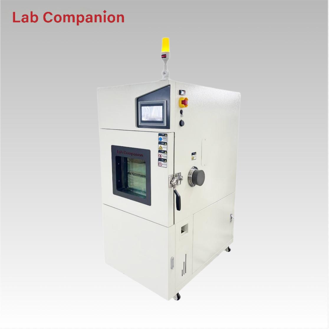
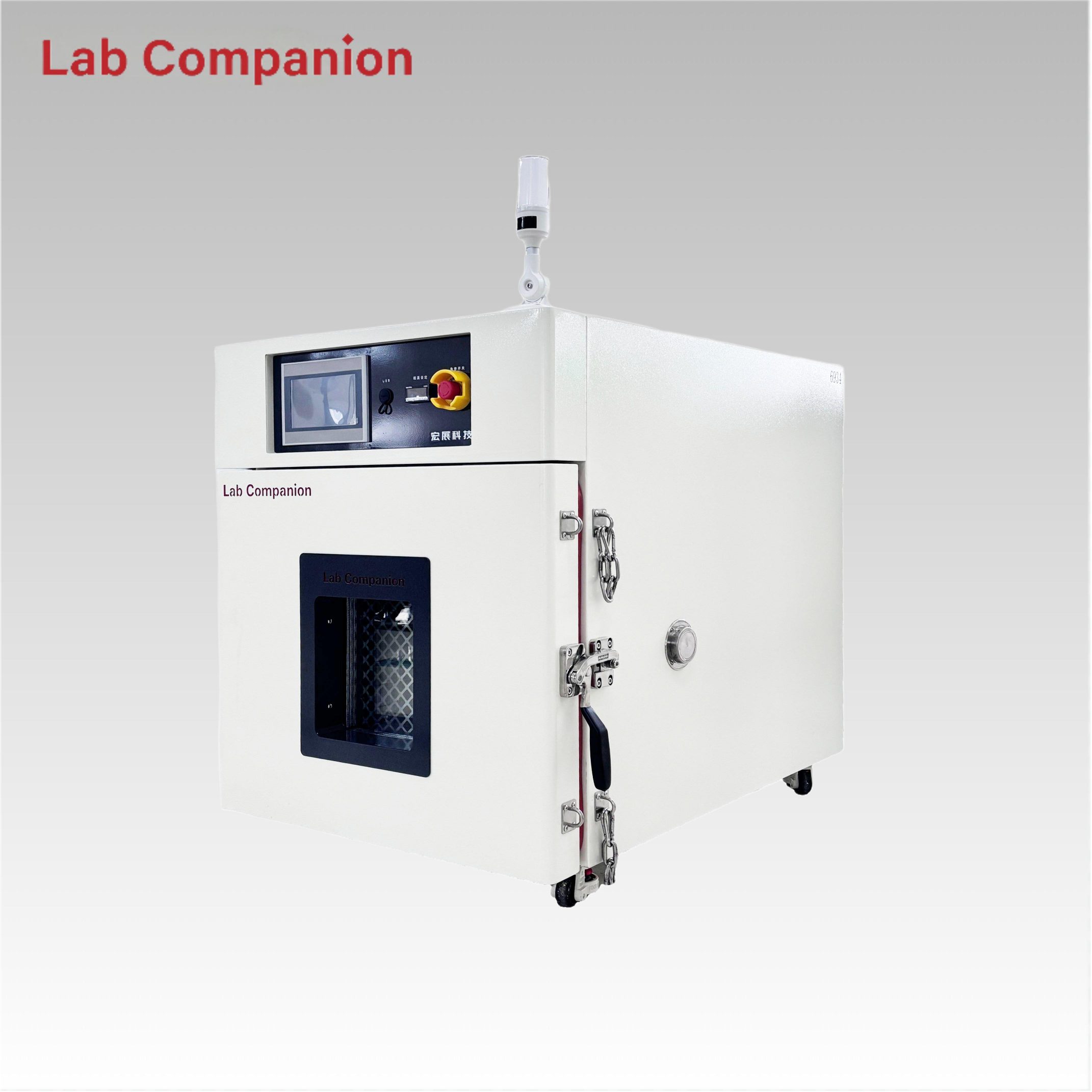
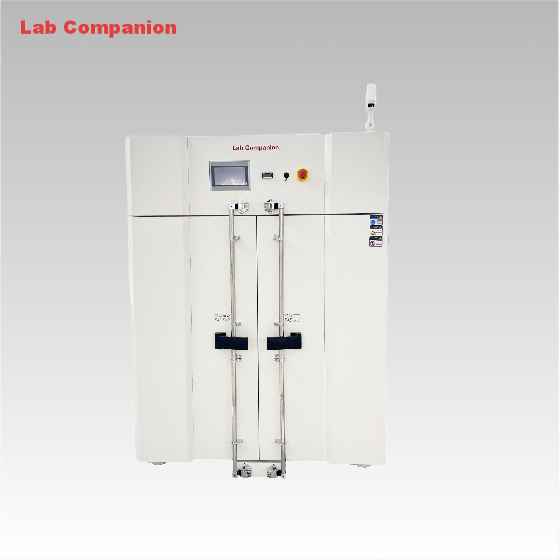
In scenarios requiring high safety and temperature control precision such as battery testing and hazardous chemical drying, explosion-proof precision ovens serve as core equipment with exclusive structural and performance advantages. They not only meet the demand for precise temperature control but also eliminate flammable and explosive hazards. The core features are analyzed below in conjunction with parameters.
I. Precise Temperature Control: Balancing Efficiency and Stability for Rigorous Test Requirements
Temperature control precision is a core competitiveness. The explosion-proof model optimizes heating efficiency and stability, suitable for sensitive scenarios like battery charging and discharging.
The equipment adopts non-linear no-load heating, with a temperature range of RT℃+15℃ to 200℃ and a heating rate of approximately 5℃ per minute. It can quickly reach the set temperature, avoid local temperature differences, and reduce sample loss and test errors.
Temperature control performance meets precision standards: fluctuation ≤±0.5℃, deviation ≤±2.0℃, and uniformity ≤2℃, with no obvious temperature dead zones. Relying on high-precision temperature sensors and an intelligent temperature control system, it realizes real-time monitoring and adjustment to ensure accurate test data.
II. Comprehensive Explosion-Proof Structure: Securing Safety from Overall to Details
Integrated explosion-proof design is a core highlight, avoiding risks comprehensively from the cabinet to accessories, suitable for high-risk scenarios such as battery overcharging and over-discharging.
The cabinet is reinforced with embedded installation to enhance structural strength against pressure impact; accessories such as explosion-proof door hinges, three-layer viewing window glass, and explosion-proof grilles balance protection and observation functions to eliminate potential safety hazards.
Equipped with an automatic pressure relief port and smoke exhaust device, it automatically relieves pressure when pressure rises and discharges harmful or flammable gases simultaneously, ensuring test safety and a clean environment.
A sealed explosion-proof power test hole is reserved for connecting an external charging and discharging test cabinet, enabling safe completion of battery overcharging, over-discharging, and charging-discharging tests, suitable for battery R&D and performance testing needs.
III. Triple Over-Temperature Protection: Multiple Prevention to Eliminate Safety Hazards
The equipment is equipped with three layers of over-temperature protection, combined with dry-burning prevention, electromagnetic locks and other protections, forming a full-process safety prevention and control system.
Three protections—over-temperature dial protection (set temperature +15℃), controller over-temperature alarm, and dry-burning prevention alarm—trigger alarms, cut off circuits or power in turn to prevent temperature runaway.
The electromagnetic lock can lock the explosion-proof door during operation, and the foolproof design avoids misoperations such as parameter setting and wiring, balancing operational convenience and safety.
IV. Adaptability to Diverse Scenarios: Professional Customization, Balancing Practicality and Compatibility
The equipment is suitable for various high-risk precision scenarios such as battery testing, hazardous chemical drying, and component aging, meeting the dual rigorous requirements of laboratory and factory R&D and testing.
The intelligent controller facilitates parameter setting and data recording; designs such as viewing windows and alarms improve operational convenience; reserved adaptation interfaces allow external equipment connection to expand the scope of use.
Summary
The core advantages of the explosion-proof precision oven lie in "precise temperature control + comprehensive explosion protection + multiple protections". It not only meets the temperature control requirements of precision tests but also solves safety pain points in high-risk scenarios, making it a reliable equipment for high-end industrial tests and R&D.
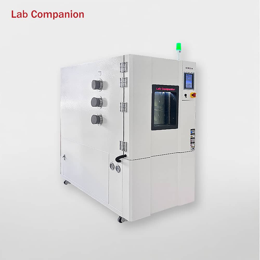
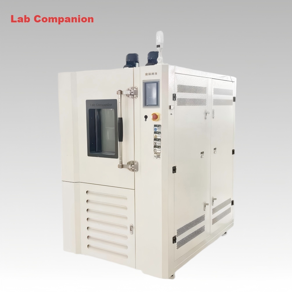
In environmental simulation testing, high-speed temperature control equipment is essential for verifying product reliability under extreme temperature variations. Guangdong Labcompanion Technology’s fast temperature change test chamber and thermal shock test chamber, both featuring high-speed temperature control, serve aerospace, military electronics, automotive new energy and other stringent industries. Though similar in core function, they have distinct principles and applicable scenarios.
Common Features
Both chambers are engineered to simulate extreme temperature fluctuations, supporting R&D and military testing. They meet international and domestic standards including GJB, MIL-STD, IEC. Fitted with Labcompanion’s intelligent control system, they enable curve programming, data export and remote monitoring. Built with robust structures and high-efficiency heating/cooling systems, some models adopt eco-friendly R404A refrigerant.
Core Differences
Item
Fast Temperature Change Test Chamber
Thermal Shock Test Chamber
Working Principle
Single-chamber, continuous & smooth gradual temperature change
Two/three-zone switching, instantaneous shock via rapid sample transfer
Key Parameters
Adjustable rate: 5–20℃/min; Temp range: -70℃–180℃; Supports humidity control
Temperature difference >150℃; Sample transfer time ≤10s; Fixed shock mode
Application Scenarios
Gradual temperature change tests for new energy batteries, automotive electronics, consumer electronics
Instant temperature shock tests for aerospace components, military equipment, automotive glass
Applicable Standards
IEC 60068-2-38, GB/T 2423.22
IEC 60068-2-14, MIL-STD-810H
Selection Recommendations
No absolute superiority exists between the two models. Select the fast temperature change chamber for gradual, adjustable temperature change tests, which offers higher cost-effectiveness for mass R&D and testing. Choose the thermal shock chamber for instantaneous extreme temperature shock tests in aerospace and military fields, with higher budget for operation and maintenance. Selection should be based on test standards, sample characteristics and budget.
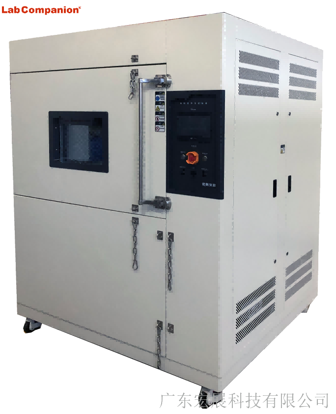
In the reliability testing of electronics, automotive and semiconductor industries, rapid temperature change and high-low temperature shock test chambers are core devices. Both simulate temperature environments but differ significantly in technical logic, test purposes and applicable scenarios. Improper selection may cause distorted test data and delayed R&D cycles. Based on practice, this article analyzes their core differences and provides scientific schemes for accurate model selection.
I. Core Technical Differences: Principles and Parameters
The core difference lies in temperature change mechanisms, leading to variations in parameters and structural design, addressing different test pain points.
(I) Working Principle: Continuous Gradient vs. Instant Switching
Rapid temperature change chambers realize stable temperature rise/fall at a set rate via cascade refrigeration and heating modules, simulating progressive temperature changes. They precisely control temperature slope to avoid overshoot.
High-low temperature shock chambers adopt a two/three-chamber structure, transferring samples between temperature zones in seconds to simulate sudden cold/heat shocks. Their core is to test material tolerance via thermal stress from sudden temperature changes.
(II) Key Parameters: Different Focuses
Rapid temperature change chambers focus on load temperature change rate, control accuracy and uniformity (typical range: -70℃~180℃), suitable for accelerated life testing and compliant with relevant standards.
High-low temperature shock chambers focus on temperature recovery time and extreme range (-80℃~200℃), with fast recovery, suitable for extreme condition simulation and equipped with sample protection.
(III) Structural Design: Single-Chamber vs. Multi-Chamber
Rapid temperature change chambers have a compact single-chamber design for space-limited laboratories and support automatic docking. Shock chambers are larger with independent zones, optimized to reduce crosstalk and customizable with explosion-proof modules.
II. Application Scenario Guide
(I) Rapid Temperature Change Test Chamber
Suitable for slow temperature changes, it is used for functional stability and accelerated life testing in automotive electronics, consumer electronics and communications.
(II) High-Low Temperature Shock Test Chamber
Suitable for instant temperature changes, it tests material and packaging reliability in semiconductors and aerospace, pre-exposing thermal expansion-related defects.
III. Selection Decision and Manufacturer Advantages
Selection core: Match product environment and test purpose — rapid chambers for gradient stability; shock chambers for extreme tolerance; large/high-heat samples prefer rapid chambers.
Domestic brand advantages: High cost-performance (lower price/energy consumption than imports), strong customization and efficient localized after-sales services.
IV. Conclusion
The two devices are complementary. Selection should align with actual working conditions, not just parameters. High-quality domestic brands provide standardized and customized solutions, supporting domestic equipment replacement for reliable testing.
In industrial testing and scientific research, Lab Companion’s environmental test chambers are essential for product reliability verification, widely applied in electronics, automotive, aerospace, home appliances and other sectors. Both chambers focus on temperature range simulation and are easily confused in selection, yet differ sharply in core functions and application scenarios. This guide clarifies their key similarities, differences and scientific selection logic for optimal matching.
I. Key Commonalities
Both are artificial environmental simulation devices for evaluating product stability in extreme temperatures, providing data support for R&D, mass production testing and quality control, and complying with GB, IEC, ISO and other international standards.
1. Overlapping temperature range: -70℃~150℃ for high and low temperature chambers, -40℃~150℃ for constant temperature and humidity chambers, covering most industrial basic temperature test needs.
2. Unified operation & precision: Equipped with intelligent control systems (supporting parameter preset, curve programming, data export); temperature control accuracy ±0.5℃, fluctuation ≤±1℃.
II. Core Differences
The fundamental distinction is the presence of a humidity control module, which defines functional boundaries, application scenarios, structure, cost and O&M:
High and Low Temperature Test Chamber
1. Core Function: Only temperature regulation (heating/cooling/constant temperature), no humidity control module
2. Typical Scenarios: Temperature-only tests, e.g., high/low temperature cycle of electronic components, temperature impact of auto parts
3. Structure: Simplified configuration (heater, refrigeration system); better thermal insulation, smaller footprint for the same specification
4. Cost & O&M: Lower procurement cost; simple routine maintenance for refrigeration/heating system only, low energy consumption
Constant Temperature and Humidity Test Chamber
1. Core Function: Dual regulation of temperature and humidity; humidity range 40%~95%RH (20%~98%RH for premium models), accuracy ±2%RH
2. Typical Scenarios: Temperature-humidity synergy tests, e.g., damp heat aging of electronics, humidity storage of medical devices, damp heat operation of home appliances
3. Structure: Complex configuration (humidification tank, dehumidifier, high-seal box); additional components for professional humidity control
4. Cost & O&M: 15%~30% higher procurement cost by specification; regular O&M for humidity parts (tank cleaning, sensor calibration), relatively higher energy consumption.
III. Selection Guide
Adhere to demand-oriented matching and balance cost performance with the following core principles:
1. Choose High and Low Temperature Test Chamber if: Only temperature change testing is needed, humidity has no impact on results, budget is limited, or laboratory space is narrow (high cost performance, easy O&M)
2. Choose Constant Temperature and Humidity Test Chamber if: Temperature-humidity synergy simulation is required, compliance with industry humidity test standards is needed, or testing moisture/corrosion-prone samples (focus on humidity parameters and reserve O&M budget)
IV. Conclusion
Lab Companion’s two test chambers both deliver stable temperature regulation for diverse industrial needs, with core differences rooted in the humidity control module. The high and low temperature chamber is ideal for basic temperature-only tests with its specialized function and cost efficiency; the constant temperature and humidity chamber excels in complex environmental simulation with its dual temperature-humidity regulation capability.
Abandon the misconception of "more functions = better". Optimal selection relies on integrating core test needs, budget, O&M capacity and laboratory space, to achieve the best balance between test effectiveness and long-term use cost. The two chambers complement each other, forming the core competitiveness of Lab Companion’s environmental test chamber series.
The precise environmental simulation capability of the temperature and humidity test chamber relies on a modular structure design of "chamber base + functional systems + control system". All components work in synergy to achieve accurate regulation and stable maintenance of temperature and humidity. The core structure is divided into the following parts:
I. Chamber Basic Structure: Core of Environmental Bearing
1. Inner Tank: As the core carrier of the test area, it is usually made of SUS 304 stainless steel for excellent corrosion resistance and easy cleaning. The smooth inner wall is equipped with one or two axial fans (quantity depends on test chamber volume), which circulate air inside the chamber to ensure uniform airflow distribution. For some models, the inner tank is treated with anti-condensation technology to prevent water dripping from affecting test results.
2. Outer Shell: Mainly constructed from galvanized steel sheets with electrostatic powder coating, it serves as protection and thermal insulation. The gap between the outer shell and inner tank is filled with dense mineral wool to minimize heat exchange between the inside and outside of the chamber, reducing energy consumption.
3. Chamber Door & Door Seal: The door is fitted with multi-layer heated glass, which allows real-time observation of test status; the heating and defrosting function prevents glass fogging. A silicone door seal is attached to the inner side of the door to ensure airtightness and avoid temperature/humidity leakage.
4. Shelves: Height-adjustable stainless steel shelves are designed for placing test samples. They ensure unobstructed air circulation around samples and do not interfere with internal airflow.
II. Temperature Control System
1. Heating Assembly: Installed near the air duct of the inner tank, it features electric heating tubes as the core component. With high temperature resistance and uniform heat generation, the tubes directly supply heat to the internal air and respond to heating commands from the controller.
2. Refrigeration System: Air conditioning components are integrated into the air handling system at the rear of the test chamber. Circulating air is cooled when passing through a heat exchanger. The condenser is generally air-cooled, with a water-cooled option available.
III. Humidity Control System
A. Humidification Device
l Electrode-type Humidifier: Consists of electrode rods and a humidification water tank (for storing distilled/deionized water). Steam is generated by heating the water when the electrode rods are energized.
B. Dehumidification Device
l Refrigeration Dehumidification Module: Linked with the evaporator, it achieves dehumidification through cooling and condensation.
l Drainage PipeCollects condensed water and discharges it outside the chamber to maintain inner tank dryness.
IV. Operation & Control System
1. Operators can send commands to the Labcompanion controller via the color LCD touchscreen to control the test chamber. Intuitive graphic symbols enable a user-friendly interface, simplifying operation without requiring additional instructions.
2. The Labcompanion controller is a self-monitoring, 32-bit digital measurement and control system specifically designed for test system applications.
Key Features
l Height-adjustable color LCD touchscreen for flexible operation.
l The program memory can store 100 test programs, with a total of up to 1000 program steps, supporting 250 program step cycles and 9999 program cycles.
l Software supports non-voltage input/output switches.
l Integrated temperature and humidity limit monitoring system.
l Connectable to host server systems via RS232-C serial interface or to network systems via TCP/IP.
l Switchable Chinese/English interface.
In summary, the structural design of the test chamber is centered on precision control, stable operation and reliability, with all components corresponding to the temperature/humidity control principles. Understanding the core components facilitates efficient equipment maintenance and troubleshooting.
With the rapid development of the new energy vehicle industry, the safety and reliability of power batteries directly determine vehicle quality. High-low temperature testing is a key link, which must strictly comply with standards such as IEC 62133 and GB/T 31484. Currently, enterprises generally face three major pain points: thermal runaway risks, difficulty in standard compliance, and insufficient non-standard adaptation. With over 20 years of experience in environmental testing equipment, Guangdong Labcompanion has launched a dedicated explosion-proof high-low temperature test chamber for new energy, providing one-stop solutions with customized and compliant advantages.
I. Core Pain Points of Power Battery High-Low Temperature Testing
High-low temperature testing is the "lifeline" of power battery R&D and mass production, with core pain points focusing on three aspects:
l High thermal runaway risks: Swelling and fire are likely during testing; traditional equipment lacks targeted explosion-proof design, easily causing safety accidents and losses.
l Difficult compliance: Insufficient temperature control accuracy and incomplete data recording of traditional equipment lead to certification rework, making it hard for SMEs to enter the mainstream market.
l Poor non-standard adaptation: Long customization cycle (3-6 months) and high cost fail to match R&D schedules and diverse needs.
II. Labcompanion’s Customized Solutions
Targeting the pain points, Labcompanion solves the dilemmas from three core dimensions based on the needs of leading enterprises:
l Full-dimensional explosion protection: Real-time battery monitoring, passive protection, and inert gas replacement to eliminate safety hazards.
l Compliance guarantee: Temperature control accuracy ±0.3℃, uniformity ≤±0.5℃, traceable data, and professional certification guidance.
l Rapid customization: Volume 36L~1000L, customization cycle shortened to 1-3 months, supporting function expansion and intelligent operation.
III. Benchmark Case & Selection Suggestions
Labcompanion’s explosion-proof test chamber helped BYD shorten the R&D cycle of solid-state batteries by 20%, successfully pass IEC 62133 certification, and achieve bulk procurement.
Key selection points: Prioritize manufacturers with complete explosion-proof qualifications, compliance with standards, and strong customization and after-sales capabilities (Labcompanion has service centers in 12 cities nationwide, with 2-hour response, 48-hour on-site support, and 3-year warranty).
IV. Conclusion
Through technological innovation, Labcompanion solves key testing pain points of power batteries, gaining trust from leading enterprises. It will continue to deepen its layout to help the high-quality development of the new energy industry.
1. Large Capacity Design
With an internal volume of 1000L, the oven provides extremely spacious inner space, which can easily accommodate a large number of items for simultaneous baking, drying, or heat treatment. It is particularly suitable for industrial production scenarios that require processing large workpieces or batches of samples, as well as commercial kitchens, bakeries, and catering institutions that need to handle high-volume ingredients, effectively improving work efficiency and meeting large-scale production needs.
2. Double-Door Structure
Adopting a double-door opening design, it greatly facilitates the loading and unloading of large-size, heavy, or bulky items, which is more convenient and efficient compared with single-door ovens. At the same time, the double-door structure can reduce the area of heat loss when opening the door, avoid drastic fluctuations in internal temperature, and ensure the stability of the baking or heat treatment process.
3. Precision Temperature Control
Generally equipped with a digital display temperature controller, and high-precision large-size touchscreen controllers are available as options for more intuitive and convenient operation. It adopts high-accuracy temperature sensors to monitor the internal temperature in real time, and combines advanced PID control technology to automatically adjust the heating power according to the temperature difference, ensuring precise temperature control with small temperature fluctuation (usually within a small range), thus guaranteeing the consistency and stability of product quality.
4. Excellent Temperature Uniformity
Equipped with high-wind-volume circulating motors and scientifically optimized air duct design (optional horizontal or vertical air supply mode), the hot air can circulate uniformly in the oven cavity. This design ensures that the temperature of each position in the oven is evenly distributed, effectively avoiding uneven heating caused by local temperature differences, and ensuring that all processed items have the same effect.
5. Multiple Safety Protection Mechanisms
Equipped with an independent over-temperature limiting and alarm system. When the internal temperature exceeds the preset safe value, the system will automatically cut off the heating power and issue an audible and visual alarm prompt to prevent potential hazards caused by overheating. In addition, it is also equipped with multiple safety safeguards such as overload protection, short-circuit protection, and grounding protection, comprehensively ensuring the safety of equipment operation and operators.
6. Reasonable and Durable Structure
The outer shell is made of cold-rolled steel plate, which is treated with powder coating, featuring excellent wear resistance, corrosion resistance, and impact resistance, and has a long service life. The inner chamber is made of high-quality SUS304 or 430 mirror-finish stainless steel, which is non-toxic, harmless, easy to clean, and can resist corrosion from moisture, grease, or chemical substances. The insulation layer adopts high-density aluminum silicate cotton or glass wool, which has excellent thermal insulation performance, can effectively reduce heat loss, save energy, and prevent the outer shell from overheating to avoid scalding.
7. High Customizability
To meet the diverse needs of different industries and processes, the oven supports personalized customization. Customers can customize the temperature range (adjust according to actual process requirements), inner chamber size (adapt to special-sized workpieces or ingredients), and multi-temperature zone design (realize different temperature control in different areas of the oven) according to their specific needs, making the equipment more in line with actual application scenarios.
Environmental Stress Screening (ESS) and Temperature Cycling (TC) are widely used reliability verification methods for electronic products, differing significantly in core principles, stress types, and application scenarios.
ESS is a multi-stress combined screening method. It efficiently identifies potential early-stage defects by applying multiple environmental stresses simultaneously, simulating the synergistic effects of real operating conditions.
TC is a single-stress screening method. It accelerates the exposure of thermal expansion/contraction-related defects through periodic temperature variations.
Key differences are as follows:
1. Stress Types & Defect Coverage
l TC: Only applies temperature cycling stress (e.g., -55°C to +125°C). Thermal stress induced by differential material expansion/contraction detects defects directly linked to thermal matching, including solder joint fatigue, poor chip bonding, package cracks, and multi-layer dielectric splitting.
l ESS: Adopts a multi-stress superimposition strategy, synchronously applying temperature cycling, random vibration, and electrical stress (e.g., dynamic voltage switching). This coupling effect effectively exposes complex failure modes such as structural loosening, poor connector contact, microcrack propagation, and intermittent conduction failure, especially intermittent faults hard to replicate under single-stress conditions.
2. Equipment Investment & Cost
l TC: Requires only temperature test chambers, with low procurement costs, standardized operation, easy maintenance, minimal energy/labor consumption, and suitability for large-scale mass production deployment.
l ESS: Demands an integrated test platform comprising temperature control systems, vibration tables, electrical stress loading modules, and high-precision monitoring systems. Initial investment typically exceeds RMB 1 million, with high-end configurations costing several million yuan. It imposes strict requirements on site, power supply, cooling systems, and technician expertise, leading to substantially higher operational costs.
3. Application Scenarios & Industry Requirements
l TC: A routine screening method widely used in consumer electronics and industrial control equipment—fields sensitive to cost or with conventional reliability needs.
l ESS: Boasting a high defect detection rate (60%–80% for intermittent faults), it is mandated by industry standards for high-reliability sectors including aerospace, automotive electronics, military equipment, and medical devices to ensure critical system functionality.
4. Screening Effectiveness
l Studies indicate TC screens 75%–85% of defects, random vibration screens 15%–25%, while their combination (core of ESS) achieves a detection rate of up to 90%.
l ESS’s multi-stress coupling better simulates real-world comprehensive stresses, enabling more thorough elimination of early-stage failures.
5. Lab Companion ESS & TC Test Chambers - Guangdong Lab Companion Co., Ltd.
High efficiency guarantees quality, maximizing reliability assurance.
Lab Companion ESS series complies with universal climatic test standards, offering chamber volumes from 270L to 1300L and a temperature range of -70°C to +180°C, meeting diverse customer needs. Optimal temperature change rates: 5K/min, 10K/min, 15K/min.
Your product functionality remains intact throughout production, R&D, and quality assurance. Leave reliability testing to us.


 Get A Quote


 IPv6 network supported