Energy-Saving Environmental Test Chamber: Safeguard Your Long-Term Product Costs
Dec 01, 2025
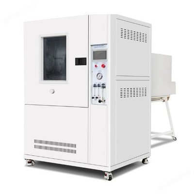
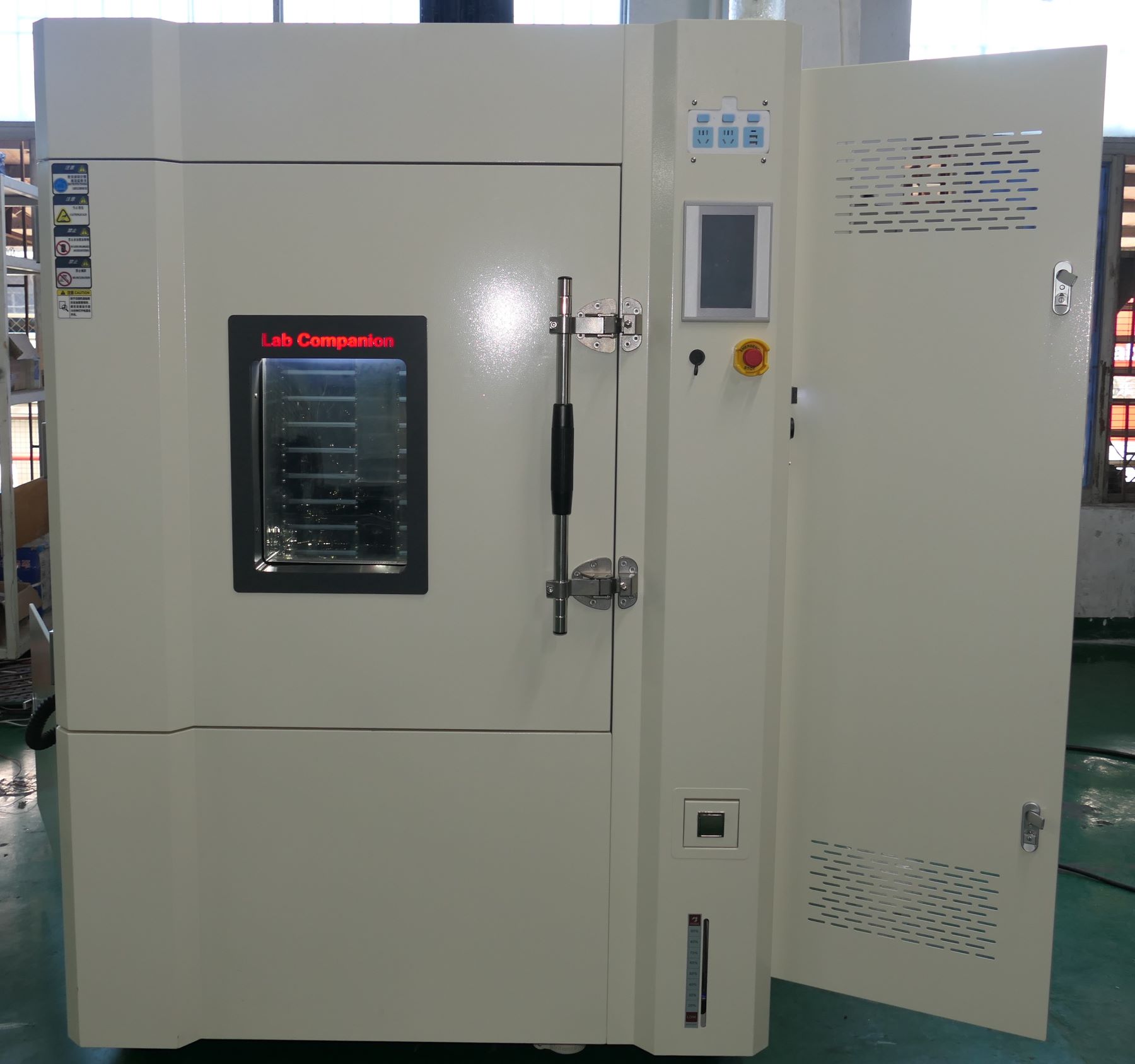
For enterprises in manufacturing, electronic technology, and related industries, product reliability testing is a critical quality assurance link. However, the operational costs of environmental test chambers—core testing equipment—are often overlooked. Many businesses focus solely on testing precision during procurement, only to be troubled by high energy bills in long-term use. Our energy-saving environmental test chamber effectively resolves the conflict between "accurate testing" and "cost control," providing comprehensive support for product lifecycle cost management.
Core Energy-Saving Feature: Intelligent Refrigeration System Regulation
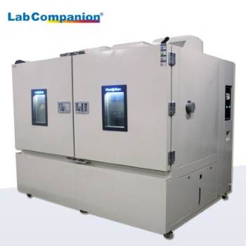
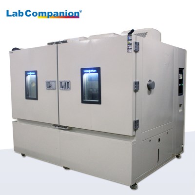
As the primary energy-consuming component of environmental test chambers, the energy regulation technology of the refrigeration system directly determines the equipment’s energy efficiency. On the premise of meeting core technical indicators, this test chamber innovatively integrates multiple energy adjustment measures to achieve intelligent dynamic control of refrigeration capacity.
The system precisely regulates evaporation temperature via the controller and links it with a hot gas bypass energy adjustment mechanism, matching refrigeration demand in real time based on the required cooling rate and target temperature range. When approaching the set low temperature, the system automatically reduces refrigeration capacity to avoid temperature overshoot—a common issue in traditional models—ensuring test stability. During the constant temperature phase, it abandons the energy-intensive "hot-cold balance" mode, optimizing energy utilization at the source. Verified in real operating conditions, the energy-saving effect reaches up to 30%, significantly reducing long-term operational costs, especially for enterprises requiring 24/7 continuous operation.
Precision & Energy Efficiency: Optimized Heating System Power Control
Refined control of the heating system further enhances the equipment’s energy-saving advantages and temperature control precision. The system adopts a synergistic control scheme of temperature controllers and thyristors: the temperature controller collects real-time temperature signals and issues control commands, while thyristors precisely adjust the heater’s power output.
When the temperature is far below the set value, thyristors deliver full power for rapid heating. As the temperature gradually approaches the set value, the output power decreases incrementally; once the target temperature is reached, power output stops immediately. This on-demand power distribution mode eliminates energy waste and ensures precise temperature control, providing a stable and reliable temperature environment for tests.
For example: When the internal temperature is significantly lower than the set value, thyristors operate at full power, and the heater runs at maximum load to ensure rapid temperature rise. As the temperature nears the target, the thyristor’s output power gradually decreases. Once the target temperature is achieved, the thyristor stops power output immediately, and the heater enters standby mode. This "on-demand power supply" mode eliminates the drawback of "frequent start-stop" in traditional heating systems—avoiding ineffective energy consumption while greatly improving temperature control precision, making it particularly suitable for test scenarios requiring high temperature stability.
Dual-System Synergy: Safeguard Enterprise Costs
From the refrigeration system’s intelligent energy adjustment to the heating system’s precision power control, our environmental test chamber centers on dual-system collaborative energy-saving technology. While ensuring accurate test data, it maximizes energy cost reduction. Choosing our test chamber not only guarantees product testing quality but also enables scientific management of enterprise operational costs, providing peace of mind throughout your product R&D and production processes.
In addition, if your enterprise is seeking a cost-effective environmental test chamber or struggling with high energy consumption from existing equipment, we recommend focusing on our energy-saving model. Let professional equipment protect your product quality while reducing costs and enhancing efficiency for your business.
Read More


 Get A Quote


 IPv6 network supported