banner
Home

Climate Test Chamber

Climate Test Chamber

  • A Brief Discussion on the Use and Maintenance of Environmental Testing Chamber
    May 10, 2025
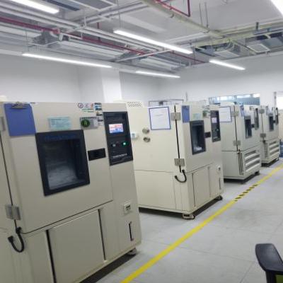
    Ⅰ. Proper Use of LABCOMPANION's Instrument Environmental testing equipment remains a type of precision and high-value instrument. Correct operation and usage not only provide accurate data for testing personnel but also ensure long-term normal operation and extend the equipment's service life.   First, before conducting environmental tests, it is essential to familiarize oneself with the performance of the test samples, test conditions, procedures, and techniques. A thorough understanding of the technical specifications and structure of the testing equipment—particularly the operation and functionality of the controller—is crucial. Carefully reading the equipment’s operation manual can prevent malfunctions caused by operational errors, which may lead to sample damage or inaccurate test data.   Second, select the appropriate testing equipment. To ensure smooth test execution, suitable equipment should be chosen based on the characteristics of the test samples. A reasonable ratio should be maintained between the sample volume and the effective chamber capacity of the test chamber. For heat-dissipating samples, the volume should not exceed one-tenth of the chamber’s effective capacity. For non-heating samples, the volume should not exceed one-fifth. For example, a 21-inch color TV undergoing temperature storage testing may fit well in a 1-cubic-meter chamber, but a larger chamber is required when the TV is powered on due to heat generation.   Third, position the test samples correctly. Samples should be placed at least 10 cm away from the chamber walls. Multiple samples should be arranged on the same plane as much as possible. The placement should not obstruct the air outlet or inlet, and sufficient space should be left around the temperature and humidity sensors to ensure accurate readings.   Fourth, for tests requiring additional media, the correct type must be added according to specifications. For instance, water used in humidity test chambers must meet specific requirements: the resistivity should not be less than 500 Ω·m. Tap water typically has a resistivity of 10–100 Ω·m, distilled water 100–10,000 Ω·m, and deionized water 10,000–100,000 Ω·m. Therefore, distilled or deionized water must be used for humidity tests, and it should be fresh, as water exposed to air absorbs carbon dioxide and dust, reducing its resistivity over time. Purified water available on the market is a cost-effective and convenient alternative.   Fifth, proper use of humidity test chambers. The wet-bulb gauze or paper used in humidity chambers must meet specific standards—not just any gauze can substitute. Since relative humidity readings are derived from the dry-bulb and wet-bulb temperature difference (strictly speaking, also influenced by atmospheric pressure and airflow), the wet-bulb temperature depends on water absorption and evaporation rates, which are directly affected by the gauze quality. Meteorological standards require that wet-bulb gauze must be a specialized "wet-bulb gauze" made of linen. Incorrect gauze may lead to inaccurate humidity control. Additionally, the gauze must be installed properly: 100 mm in length, tightly wrapped around the sensor probe, with the probe positioned 25–30 mm above the water cup, and the gauze immersed in water to ensure precise humidity control.   Ⅱ. Maintenance of Environmental Testing Equipment Environmental testing equipment comes in various types, but the most commonly used are high-temperature, low-temperature, and humidity chambers. Recently, combined temperature-humidity test chambers integrating these functions have become popular. These are more complex to repair and serve as representative examples. Below, we discuss the structure, common malfunctions, and troubleshooting methods for temperature-humidity test chambers.   (1) Structure of Common Temperature-Humidity Test Chambers In addition to proper operation, test personnel should understand the equipment’s structure. A temperature-humidity test chamber consists of a chamber body, air circulation system, refrigeration system, heating system, and humidity control system. The air circulation system typically features adjustable airflow direction. The humidification system may use boiler-based or surface evaporation methods. The cooling and dehumidification system employs an air-conditioning refrigeration cycle. The heating system may use electric fin heaters or direct resistance wire heating. Temperature and humidity measurement methods include dry-wet bulb testing or direct humidity sensors. Control and display interfaces may feature separate or combined temperature-humidity controllers.   (2) Common Malfunctions and Troubleshooting Methods for Temperature-Humidity Test Chambers 1.High-Temperature Test Issues   If the temperature fails to reach the set value, inspect the electrical system to identify faults. If the temperature rises too slowly, check the air circulation system, ensuring the damper is properly adjusted and the fan motor is functioning. If temperature overshooting occurs, recalibrate the PID settings. If the temperature spikes uncontrollably, the controller may be faulty and require replacement.   2.Low-Temperature Test Issues   If the temperature drops too slowly or rebounds after reaching a certain point:                Ensure the chamber is pre-dried before testing.                Verify that samples are not overcrowded, obstructing airflow.                If these factors are ruled out, the refrigeration system may need professional servicing. Temperature rebound is often due to poor ambient conditions (e.g., insufficient clearance behind the chamber or high ambient temperature).   3.Humidity Test Issues   If humidity reaches 100% or significantly deviates from the target:                  For 100% humidity: Check if the wet-bulb gauze is dry. Inspect the water level in the wet-bulb sensor’s reservoir and the automatic water supply system. Replace or clean hardened gauze if necessary.                  For low humidity: Verify the humidification system’s water supply and boiler level. If these are normal, the electrical control system may require professional repair.   4.Emergency Faults During Operation   If the equipment malfunctions, the control panel will display an error code with an audible alarm. Operators can refer to the troubleshooting section in the manual to identify the issue and arrange for professional repairs to resume testing promptly.   Other environmental testing equipment may exhibit different issues, which should be analyzed and resolved case by case. Regular maintenance is essential, including cleaning the condenser, lubricating moving parts, and inspecting electrical controls. These measures are indispensable for ensuring equipment longevity and reliability.
    Read More
  • User Guide for Environmental Test Equipment
    Apr 26, 2025
    1. Basic Concepts Environmental test equipment (often referred to as "climate test chambers") simulates various temperature and humidity conditions for testing purposes.                                                                                    With the rapid growth of emerging industries such as artificial intelligence, new energy, and semiconductors, rigorous environmental testing has become essential for product development and validation. However, users often face challenges when selecting equipment due to a lack of specialized knowledge.   The following will introduce the basic parameters of the environmental test chamber, so as to help you make a better choice of products.   2. Key Technical Specifications (1) Temperature-Related Parameters 1. Temperature Range   Definition: The extreme temperature range in which the equipment can operate stably over long periods.   High-temperature range:  Standard high-temperature chambers: 200℃, 300℃, 400℃, etc.  High-low temperature chambers: High-quality models can reach 150–180℃. Practical recommendation: 130℃ is sufficient for most applications.   Low-temperature range: Single-stage refrigeration: Around -40℃. Cascade refrigeration: Around -70℃. Budget-friendly options: -20℃ or 0℃.                                         2. Temperature Fluctuation   Definition: The variation in temperature at any point within the working zone after stabilization.   Standard requirement: ≤1℃ or ±0.5℃.   Note: Excessive fluctuation can negatively impact other temperature performance metrics.   3. Temperature Uniformity   Definition: The maximum temperature difference between any two points in the working zone.   Standard requirement: ≤2℃.   Note: Maintaining this precision becomes difficult at high temperatures (>200℃).   4. Temperature Deviation   Definition: The average temperature difference between the center of the working zone and other points.   Standard requirement: ±2℃ (or ±2% at high temperatures).   5. Temperature Change Rate   Purchasing advice: Clearly define actual testing requirements. Provide detailed sample information (dimensions, weight, material, etc.). Request performance data under loaded conditions.(How many produce you going to test once?) Avoid relying solely on catalog specifications.   (2) Humidity-Related Parameters 1. Humidity Range   Key feature: A dual parameter dependent on temperature.   Recommendation: Focus on whether the required humidity level can be maintained stably.   2. Humidity Deviation   Definition: The uniformity of humidity distribution within the working zone.   Standard requirement: ±3%RH (±5%RH in low-humidity zones).   (3) Other Parameters 1. Airflow Speed   Generally not a critical factor unless specified by testing standards.   2. Noise Level   Standard values: Humidity chambers: ≤75 dB. Temperature chambers: ≤80 dB.   Office environment recommendations: Small equipment: ≤70 dB. Large equipment: ≤73 dB.   3. Purchasing Recommendations Select parameters based on actual needs—avoid over-specifying. Prioritize long-term stability in performance. Request loaded test data from suppliers. Verify the true effective dimensions of the working zone. Specify special usage conditions in advance (e.g., office environments).
    Read More
  • Summary for LED Testing Conditions
    Apr 22, 2025
    What is LED? A Light Emitting Diode (LED) is a special type of diode that emits monochromatic, discontinuous light when a forward voltage is applied—a phenomenon known as electroluminescence. By altering the chemical composition of the semiconductor material, LEDs can produce near-ultraviolet, visible, or infrared light. Initially, LEDs were primarily used as indicator lights and display panels. However, with the advent of white LEDs, they are now also employed in lighting applications. Recognized as the new light source of the 21st century, LEDs offer unparalleled advantages such as high efficiency, long lifespan, and durability compared to traditional light sources. Classification by Brightness: Standard Brightness LEDs (made from materials like GaP, GaAsP) High-Brightness LEDs (made from AlGaAs) Ultra-High-Brightness LEDs (made from other advanced materials) ☆ Infrared Diodes (IREDs): Emit invisible infrared light and serve different applications.   LED Reliability Testing Overview: LEDs were first developed in the 1960s and were initially used in traffic signals and consumer products. It is only in recent years that they have been adopted for lighting and as alternative light sources. Additional Notes on LED Lifespan: The lower the LED junction temperature, the longer its lifespan, and vice versa. LED lifespan under high temperatures: 10,000 hours at 74°C 25,000 hours at 63°C As an industrial product, LED light sources are required to have a lifespan of 35,000 hours (guaranteed usage time). Traditional light bulbs typically have a lifespan of around 1,000 hours. LED streetlights are expected to last over 50,000 hours.                         LED Testing Conditions Summary: Temperature Shock Test Shock Temp. 1 Room Temp Shock Temp. 2 Recovery Time Cycles Shock Method Remarks -20℃(5 min) 2 90℃(5 min)   2 Gas Shock   -30℃(5 min) 5 105℃(5 min)   10 Gas Shock   -30℃(30 min)   105℃(30 min)   10 Gas Shock   88℃(20 min)   -44℃(20 min)   10 Gas Shock   100℃(30 min)   -40℃(30 min)   30 Gas Shock   100℃(15 min)   -40℃(15 min) 5 300 Gas Shock HB-LEDs 100℃(5 min)   -10℃(5 min)   300 Liquid Shock HB-LEDs   LED High-Temperature High-Humidity Test (THB Test) Temperature/Humidity Time Remarks 40℃/95%R.H. 96 Hour   60℃/85%R.H. 500 Hour LED Lifespan Testing 60℃/90%R.H. 1000 Hour LED Lifespan Testing 60℃/95%R.H. 500 Hour LED Lifespan Testing 85℃/85%R.H. 50 Hour   85℃/85%R.H. 1000 Hour LED Lifespan Testing   Room Temperature Lifespan Test 27℃ 1000 Hour Continuous illumination at constant current   High-Temperature Operating Life Test (HTOL Test) 85℃ 1000 Hour Continuous illumination at constant current 100℃ 1000 Hour Continuous illumination at constant current   Low-Temperature Operating Life Test (LTOL Test) -40℃ 1000 Hour Continuous illumination at constant current -45℃ 1000 Hour Continuous illumination at constant current   Solderability Test Test Condition Remarks The pins of the LED (1.6 mm away from the bottom of the colloid) are immersed in a tin bath at 260 °C for 5 seconds.   The pins of the LED (1.6 mm away from the bottom of the colloid) are immersed in a tin bath at 260+5 °C for 6 seconds.   The pins of the LED (1.6 mm away from the bottom of the colloid) are immersed in a tin bath at 300 °C for 3 seconds.     Reflow soldering oven test 240℃ 10 seconds   Environmental test (Conduct TTW solder treatment for 10 seconds at a temperature of 240 °C ± 5 °C) Test Name Reference Standard Refer to the content of the test conditions in JIS C 7021 Recovery Cycle Number (H) Temperature Cycling Automotive Specification -40 °C ←→ 100 °C, with a dwell time of 15 minutes  5 minutes 5/50/100 Temperature Cycling   60 °C/95% R.H, with current applied   50/100 Humidity Reverse Bias MIL-STD-883 Method 60 °C/95% R.H, 5V RB   50/100  
    Read More
  • Comparison of Climatic Test and Environmental Test Comparison of Climatic Test and Environmental Test
    Sep 19, 2024
    Comparison of Climatic Test and Environmental Test Climate environment test -- constant temperature and humidity test chamber, high and low temperature test chamber, cold and hot shock test chamber, wet and heat alternating test chamber, rapid temperature change test chamber, linear temperature change test chamber, walk-in constant temperature and humidity test chamber, etc. They all involve temperature control. Because there are multiple temperature control points to choose from, the climate chamber temperature control method also has three solutions: inlet temperature control, product temperature control and "cascade" temperature control. The first two are single-point temperature control, and the third is two-parameter temperature control. Single point temperature control method has been very mature and widely used. Most of the early control methods were "ping-pong" switch control, commonly known as heating when it's cold and cooling when it's hot. This control mode is a feedback control mode. When the temperature of the circulating air flow is higher than the set temperature, the electromagnetic valve of refrigeration is opened to deliver cold volume to the circulating air flow and reduce the temperature of the air flow. Otherwise, the circuit switch of the heating device is switched on to directly heat the circulating air flow. Raise the temperature of the air stream. This control mode requires that the refrigeration device and heating components of the test chamber are always in a standby working state, which not only wastes a lot of energy, but also the controlled parameter (temperature) is always in an "oscillation" state, and the control accuracy is not high. Now the single-point temperature control method is mostly changed to the universal proportional differential integral (PID) control method, which can give the controlled temperature correction according to the past change of the controlled parameter (integral control) and the change trend (differential control), which not only saves energy, but also the "oscillation" amplitude is small and the control accuracy is high. Dual-parameter temperature control is to collect the temperature value of the air inlet of the test chamber and the temperature value near the product at the same time. The air inlet of the test chamber is very close to the installation position of the evaporator and heater in the air modulation room, and its magnitude directly reflects the air modulation result. Using this temperature value as the feedback control parameter has the advantage of quickly modulating the status parameters of the circulating air. The temperature value near the product indicates the real temperature environmental conditions suffered by the product, which is the requirement of the environmental test specification. Using this temperature value as the parameter of feedback control can ensure the effectiveness and credibility of the temperature environmental test, so this approach takes into account the advantages of both and the requirements of the actual test. The dual-parameter temperature control strategy can be the independent "time-sharing control" of the two groups of temperature data, or the weighted two temperature values can be combined into one temperature value as a feedback control signal according to a certain weighting coefficient, and the value of the weighting coefficient is related to the size of the test chamber, the wind speed of the circulating air flow, the size of the temperature change rate, the heat output of the product work and other parameters. Because heat transfer is a complex dynamic physical process, and is greatly affected by the atmospheric environment conditions around the test chamber, the working state of the tested sample itself, and the complexity of the structure, it is difficult to establish a perfect mathematical model for the temperature and humidity control of the test chamber. In order to improve the stability and accuracy of control, fuzzy logic control theory and method are introduced in the control of some temperature test chambers. In the control process, the thinking mode of human is simulated, and the predictive control is adopted to control the temperature and humidity space field more quickly. Compared with the temperature, the selection of humidity measurement and control points is relatively simple. During the circulation flow of the well-regulated humid air into the high and low temperature cycle test chamber, the exchange of water molecules between the wet air and the test piece and the four walls of the test chamber is very small. As long as the temperature of the circulating air is stable, the circulating air flow from entering the test chamber to exiting the test chamber is in the process. The moisture content of wet air changes very little. Therefore, the relative humidity value of the detected air at any point of the circulating air flow field in the test box, such as the inlet, the middle stream of the flow field or the return air outlet, is basically the same. Because of this, in many test chambers that use the wet and dry bulb method to measure humidity, the wet and dry bulb sensor is installed at the return air outlet of the test chamber. Moreover, from the structural design of the test box and the convenience of maintenance in use, the wet and dry bulb sensor used for relative humidity measurement and control is placed at the return air inlet for easy installation, and also helps to regularly replace the wet bulb gauze and clean the temperature sensing head of the resistance PT100, and according to the requirements of the GJB150.9A wet heat test 6.1.3. The wind speed passing through the wet-bulb sensor should not be lower than 4.6m/s. The wet-bulb sensor with a small fan is installed at the return air outlet for easier maintenance and use.      
    Read More

leave a message

leave a message
If you are interested in our products and want to know more details,please leave a message here,we will reply you as soon as we can.
submit

home

products

WhatsApp

contact us