Across electronics, new energy, automotive components, hardware and plastics, aerospace, scientific research and testing, and many other industries, the stability, reliability, and durability of products in complex natural environments such as high temperature, high humidity, and temperature-humidity cycling directly determine product quality, service life, and market reputation. As core equipment for environmental reliability testing, high temperature and humidity test chambers undertake the critical mission of simulating extreme temperature and humidity conditions, identifying product defects in advance, and verifying product compliance. With years of deep cultivation in the environmental test equipment industry, Lab Companion relies on profound technical accumulation, strict production standards, and a comprehensive service system to develop a series of high temperature and humidity test chambers. These products stand out as the preferred choice for quality testing in the industry with their precise temperature and humidity control, stable and durable performance, and strong adaptability, helping thousands of enterprises control product quality and overcome industry testing pain points.
1. Industry Imperative: High Temperature and Humidity Testing, the Touchstone of Product Quality
With the upgrading of the manufacturing industry and the continuous improvement of product quality standards, environmental reliability testing before product delivery has become an essential step. High temperature and humidity environments are common triggers for product aging and failure: electronic components are prone to short circuits, oxidation, and performance degradation under high temperature and humidity; new energy batteries may suffer from seal failure and capacity decline in damp heat conditions; automotive interiors and plastic parts are likely to deform, crack, and fade; scientific research samples and precision instruments are easily damaged and produce data deviations in humid and hot environments.
Traditional simple temperature and humidity testing equipment generally suffers from problems such as asynchronous temperature and humidity control, low control accuracy, poor uniformity, easy condensation, and high failure rates, leading to distorted test data and invalid test results. This not only delays product R&D and launch cycles but also hides potential product quality hazards. Targeting these industry pain points, Lab Companion focuses on core high temperature and humidity testing needs, and its series of test chambers fully comply with national and international testing standards including GB and IEC. They can stably simulate an ultra-wide temperature range of -40°C to 150°C and a full humidity range of 20%RH to 98%RH, perfectly meeting the needs of damp heat aging, temperature-humidity cycling, and constant damp heat testing for various products, providing solid support for product quality control.
2. Core Technical Breakthroughs: Solving Industry Challenges, Achieving Precise Temperature and Humidity Coordination
The core competitiveness of Lab Companion high temperature and humidity test chambers stems from independently developed core control technologies, which completely solve the common industry problems of traditional equipment such as "asynchronous temperature and humidity, inaccurate humidity control, and large local temperature differences", realizing stable, uniform, and precise simulation of high temperature and humidity environments.
2.1 Dual PID Collaborative Control System, Synchronous Temperature and Humidity Without Lag
The equipment is equipped with Lab Companion's independently developed C100 intelligent controller, paired with a patented dual PID temperature and humidity collaborative control system and fuzzy logic algorithm. Abandoning the traditional separate control design, it realizes linkage regulation and real-time compensation of the four modules: heating, refrigeration, humidification, and dehumidification. Temperature and humidity parameters rise, fall, and stabilize synchronously with a response time of ≤30 seconds, completely eliminating the problems of humidity lag during heating and sudden humidity drop during cooling in traditional equipment. The temperature control accuracy reaches ±0.3°C, and humidity control accuracy reaches ±2%RH, with temperature and humidity fluctuations far better than industry standards, ensuring the test environment is highly consistent with real extreme scenarios and test data is accurate and reliable.
2.2 Triple Anti-Condensation Technology, Protecting Test Samples Safely
To address the common issues of chamber condensation and water dripping that damage samples during high temperature and humidity testing, Lab Companion has innovatively created a triple anti-ondensation system: preheating air duct + exclusive hydrophobic coating + balanced air circulation. Anti-condensation coatings are sprayed on key parts such as the inner tank and chamber door, and the optimized air duct design ensures uniform air distribution, with no condensation or water accumulation throughout the test. This avoids damage to precision samples caused by condensation, making it especially suitable for testing humidity-sensitive samples such as electronic chips, precision components, and new energy materials.
2.3 High-Efficiency Air Duct Design, Maximizing Temperature and Humidity Uniformity
Adopting a vortex guide air duct paired with a high-wind-speed centrifugal fan, the air circulation frequency inside the chamber reaches 50 times per minute. Combined with a honeycomb air diffusion structure, it eliminates local temperature and humidity dead corners. Under no-load conditions, the temperature field uniformity is ≤±1.5°C, and humidity field uniformity is ≤±3%RH, ensuring consistent temperature and humidity parameters in every test area inside the chamber. Regardless of sample size or placement position, a uniform test environment is guaranteed, ensuring consistent results for batch testing.
3. Robust Hardware Configuration: Full-Line SUS316 Stainless Steel, Upgraded Durability
Lab Companion always adheres to the principle of "quality first". All high temperature and humidity test chambers are equipped with world-renowned brand core components and high-quality materials, balancing durability, stability, and energy efficiency. Core materials are fully upgraded to SUS316 stainless steel, with performance far exceeding conventional standards, meeting the long-term, high-frequency, and high-intensity testing needs of laboratories and production workshops.
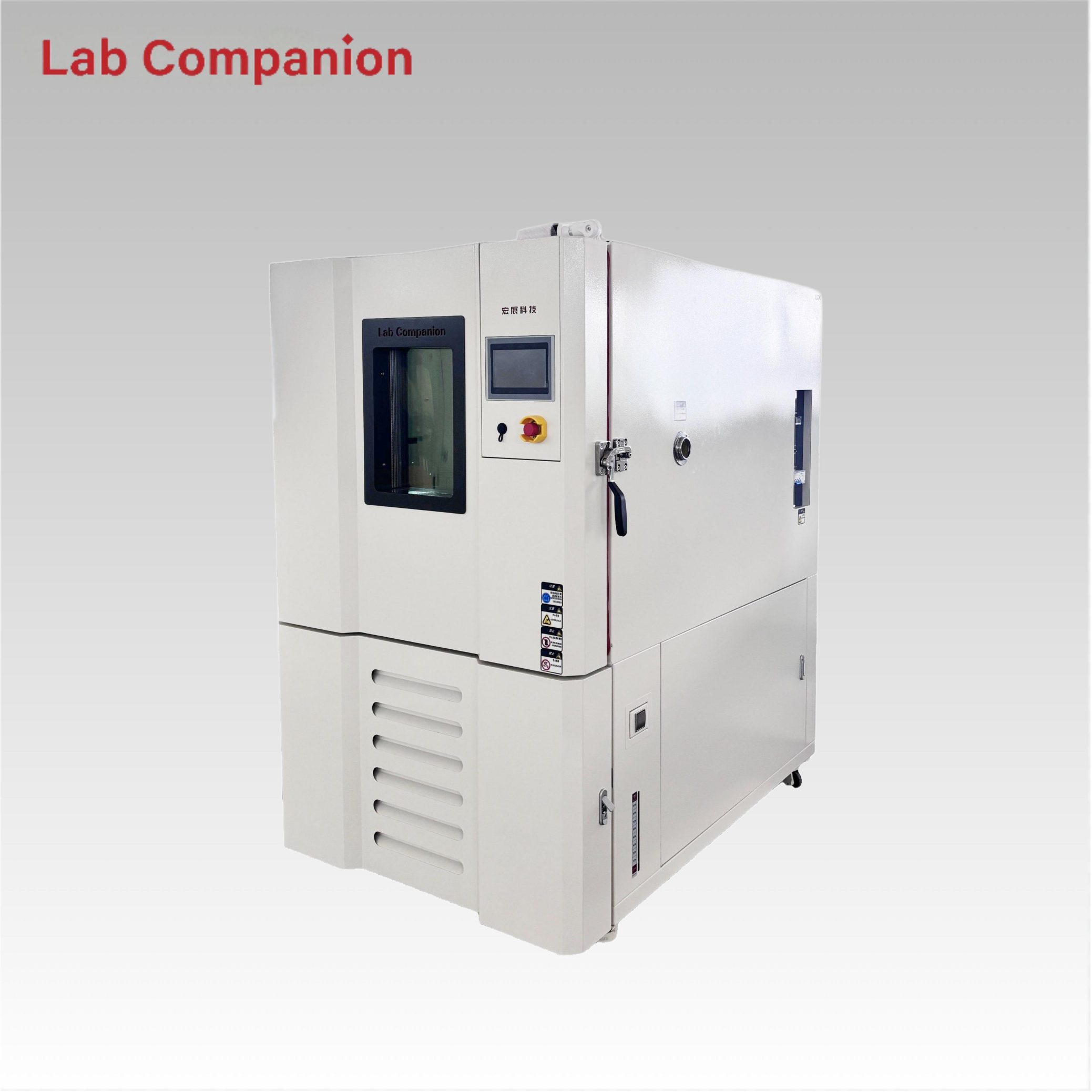
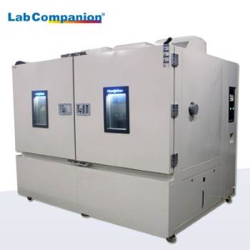
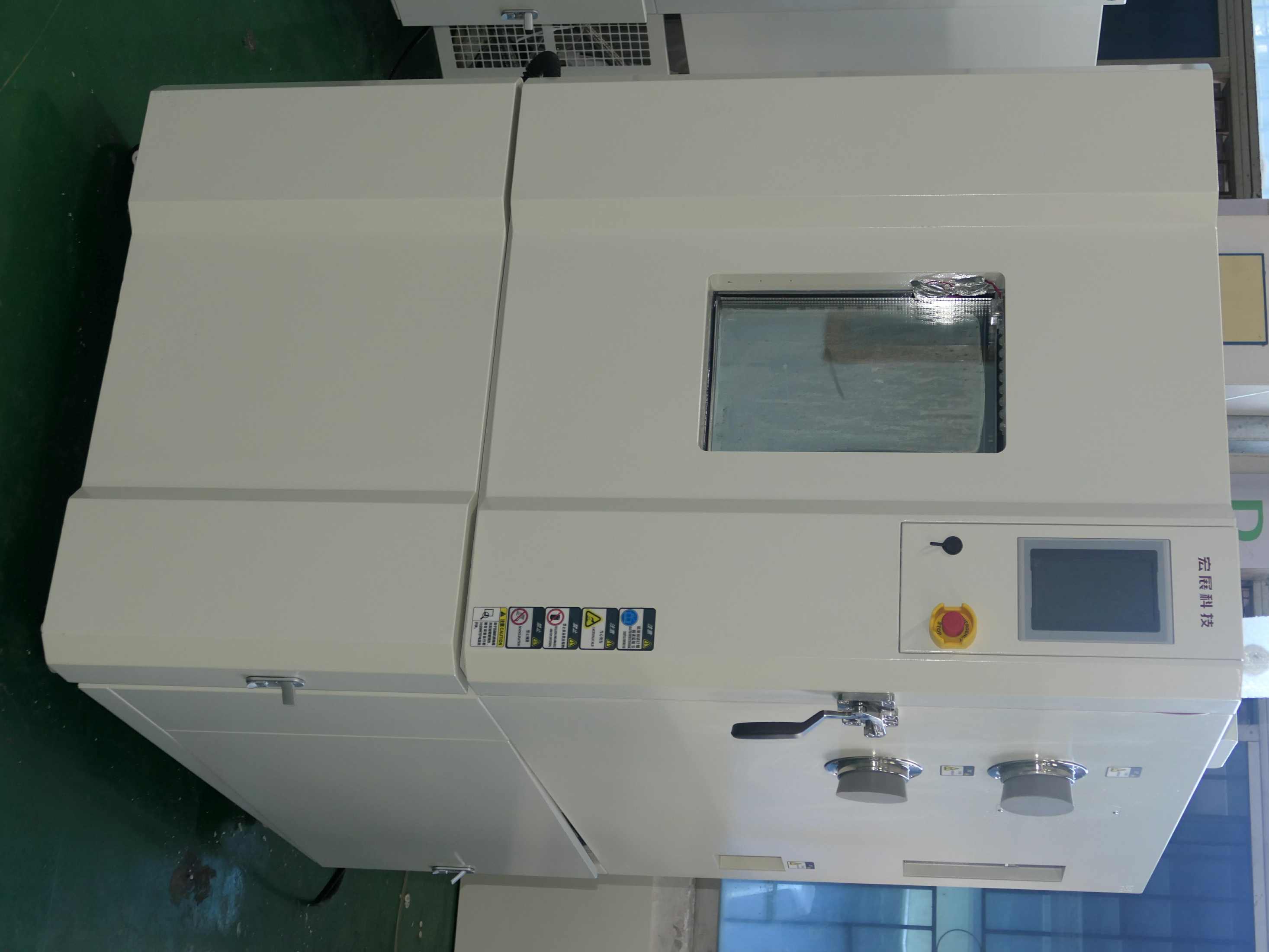
• SUS316 Stainless Steel Inner Tank and Chamber Structure The inner tank is made of SUS316 stainless steel, a high-end corrosion-resistant stainless steel with added molybdenum element and higher chromium and nickel content compared to conventional 304 stainless steel. Its high temperature resistance, high humidity resistance, and acid and alkali corrosion resistance are significantly improved. It is particularly suitable for long-term high temperature and humidity testing environments with trace corrosive media, not easy to rust or corrode by water vapor, with a smooth and easy-to-clean inner wall and no residual stains. Its service life far exceeds that of ordinary stainless steel inner tanks, maintaining intact condition after long-term operation. The outer shell of the chamber is made of high-quality steel plate with plastic spraying, sturdy and wear-resistant, with a simple and elegant appearance, stable overall structure, no shaking and low noise during operation, adapting to multiple application scenarios in laboratories and production workshops.
• SUS316 Stainless Steel Grating Sample Rack, Flexible and Secure The matching grating sample rack is also made of SUS316 stainless steel, achieving high-standard matching from material to details, completely eliminating the risk of corrosion and oxidation caused by contact between different materials. The sample rack supports free height adjustment, allowing flexible adjustment of placement space according to sample size and stacking requirements. Whether it is small test pieces, medium-sized components, or large equipment, the test position can be accurately positioned to make full use of the effective space inside the chamber. Each rack has a load capacity of up to 20kg, stably carrying various samples to ensure sample stability and fixed position during testing, guaranteeing the accuracy and reliability of test data.
• High-Performance Refrigeration and Humidification System The refrigeration system selects imported brand compressors such as German Bitzer and American Copeland, paired with environmentally friendly refrigerants, featuring high refrigeration efficiency, low energy consumption, and stable operation, with trouble-free operation under low temperature working conditions. The humidification system adopts integrated boiler steam humidification, with uniform humidification and fast response, paired with a water recovery and filtration device to greatly reduce water consumption, extend the service life of humidifying components, and reduce operation and maintenance costs.
• Full-Size Volume Options, Customized Adaptation Standard volume models are available including 36L, 64L, 80L, 150L, 408L, and up to 1000L, and customized non-standard sizes and walk-in high temperature and humidity rooms are also supported. Whether it is small precision components and test pieces, medium-sized assemblies, large automotive parts, battery packs, or complete equipment, the test space needs can be accurately matched, perfectly adapting to the diverse testing scenarios of enterprises of different scales, R&D laboratories, and quality inspection centers, avoiding space waste and testing limitations.
• User-Friendly Operation Design Equipped with a large-size high-definition touch screen andChinese-English bilingual menu, it is simple and easy to operate, supporting program editing, cycle testing, timed start, data recording, fault alarm and other functions. The chamber door is equipped with a large-view observation window and built-in lighting, allowing real-time observation of sample testing status without opening the door. Paired with the height-adjustable SUS316 stainless steel sample rack, it achieves an efficient testing experience of "precise placement + real-time observation".
4. Comprehensive Safety Protection + Full-Cycle Service, Worry-Free Use
As one of the first enterprises in China to obtain CE certification for environmental test equipment, Lab Companion has built a comprehensive safety protection system for its high temperature and humidity test chambers, equipped with more than ten safety devices including compressor overpressure/overcurrent/overheating protection, heater overload protection, water shortage protection, leakage protection, over-temperature protection, and phase sequence protection. The equipment automatically alarms and shuts down in case of abnormalities, fully protecting the safe operation of the equipment and the personal safety of operators.
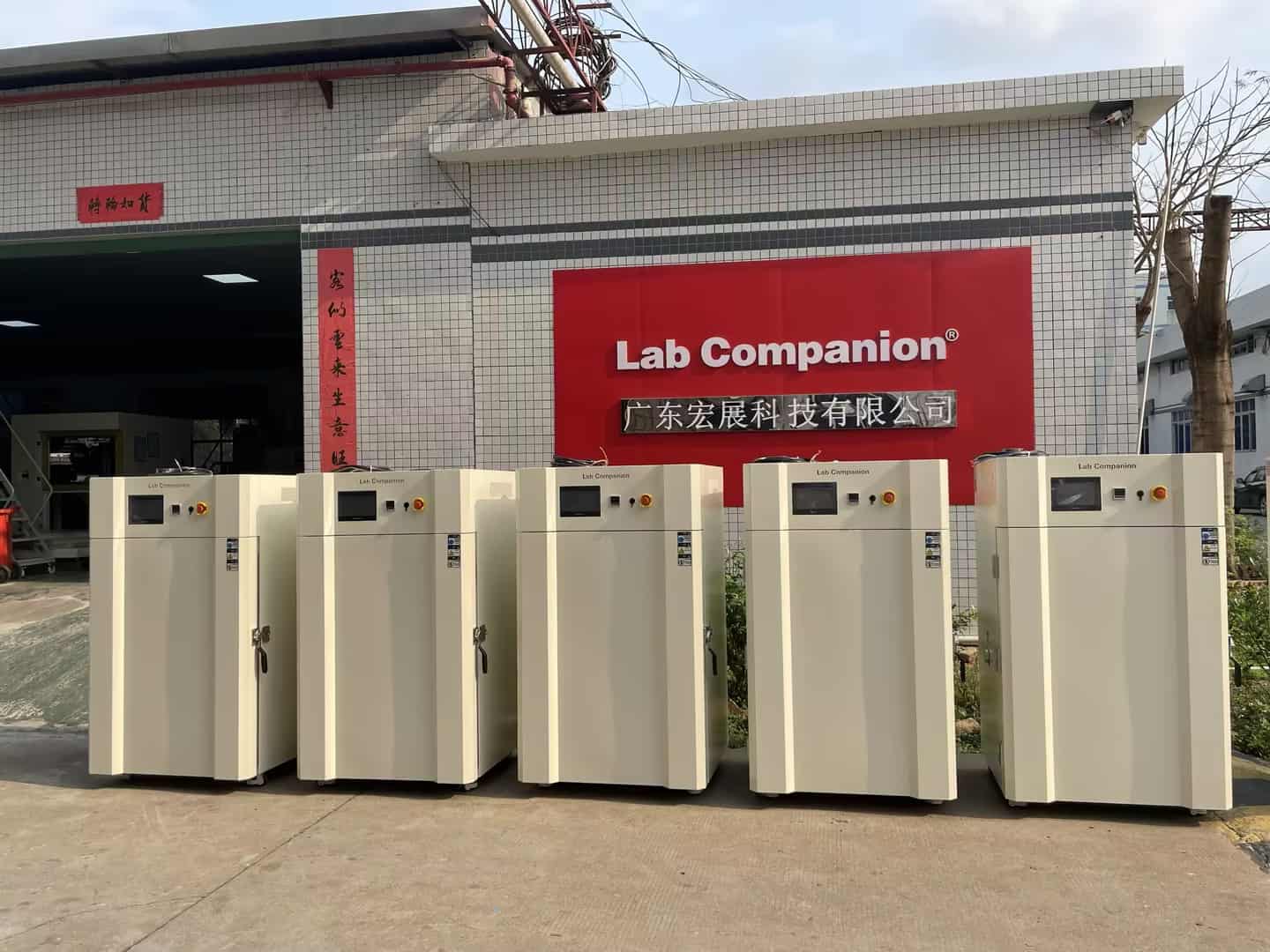
At the same time, Lab Companion has built a nationwide after-sales service network, with sales and after-sales service centers set up in Beijing, Shanghai, Chongqing, Chengdu, Wuhan, Xi'an and other major cities. It provides full-cycle services including equipment installation and commissioning, operation training, regular maintenance, fault repair, and parts replacement, with timely and efficient response, completely eliminating users' after-sales concerns. The company has passed ISO9001 quality management system certification and ISO14000 environmental management system certification. Each equipment undergoes strict performance testing and trouble-free trial operation before delivery, ensuring stable use upon arrival. Some models have even won customer recognition for continuous use for twenty years.
5. Diverse Application Scenarios, Covering Full Industry Testing Needs
With excellent performance and wide adaptability, Lab Companion high temperature and humidity test chambers are widely used in electronics, new energy, automotive manufacturing, hardware and plastics, aerospace, scientific research institutions, quality inspection centers and other fields. They have become long-term cooperative equipment for leading enterprises such as Huawei and BYD, as well as various scientific research and testing institutions. They can perfectly implement domestic and international standard tests such as GB/T 2423.3 and IEC 60068-2-78, helping products pass quality certification and enhance market competitiveness.
• Electronics Industry: Damp heat aging and reliability testing of PCBs, chips, connectors, and sensors;
• New Energy Industry: Temperature-humidity cycling and sealing performance testing of lithium batteries, energy storage modules, and photovoltaic components;
• Automotive Industry: High and low temperature damp heat cycling testing of interior parts, dashboards, chassis components, and automotive electronics;
• Materials Industry: Damp heat aging and weather resistance testing of plastics, rubber, coatings, and metal materials;
• Scientific Research and Testing: Environmental simulation experiments and sample performance testing in university laboratories and quality inspection institutions.
6. Conclusion: Empowering Quality Upgrading in Manufacturing with Professional Technology
From core technology R&D to full-line SUS316 stainless steel material upgrade, from height-adjustable high-precision sample rack design to full-cycle after-sales service, Lab Companion has always focused on the environmental test equipment industry, crafting high-quality high temperature and humidity test chambers with ingenuity. With precise, stable, and reliable performance, it safeguards product quality control for enterprises. Facing the new requirements of high-quality development in the manufacturing industry, Lab Companion will continue to focus on technological innovation, continuously optimize product performance, help various industries break through environmental testing bottlenecks, enhance core product competitiveness, and become a trusted partner for environmental test equipment.
In environmental reliability testing, temperature test chambers and thermal shock test chambers are two core instruments designed to verify the performance stability of products under extreme temperature conditions. However, they differ significantly in temperature change mode, test objectives, core parameters, and application scenarios.
As a national high-tech enterprise with over 20 years of industry experience, Lab Companion. leverages mature R&D and manufacturing capabilities to provide comprehensive environmental testing solutions across multiple industries. This article compares the two types of chambers from three dimensions: core parameters, structural design, and application scenarios, and offers targeted selection advice based on Lab Companion’s product features to help enterprises select the optimal testing equipment.
1. Core Performance Parameters: Fundamental Difference Between Gradual & Sudden Temperature Change
The core distinction between the two instruments lies in their design positioning for temperature change modes:
• Temperature Test Chamber: Gradual temperature change, steady-state constant temperature
• Thermal Shock Test Chamber: Sudden temperature shock, rapid switching
1.1 Temperature Range & Temperature Change Rate
Temperature Test Chamber
• Temperature range: Standard -70℃ ~ 150℃; customizable up to -100℃ ~ 200℃
• Temperature change feature: Average gradual rate; standard heating ≈ 5℃/min, cooling ≈ 3℃/min
• Rapid temperature change model: Equipped with dual-stage compression + eco-friendly refrigerant, with a rate of up to 20℃/min, suitable for accelerated aging tests
Lab Companion Thermal Shock Test Chamber (TS Series)
• Temperature range: Standard -65℃ ~ 150℃; customizable to -80℃ ~ 200℃
• Core advantage: Instant temperature switching (instead of average rate)
• Two-zone (TS2): Temperature transfer time ≤ 30 seconds, ≤ 10 seconds for small samples
• Three-zone (TS3): Equipped with pre-heating & pre-cooling chamber design, featuring higher switching efficiency and more stable shock performance
1.2 Temperature Uniformity & Fluctuation
Temperature Test Chamber
• Focuses on the accuracy of steady-state temperature field
• No-load uniformity ≤ ±2℃ (up to ±1.5℃)
• Fluctuation ≤ ±0.5℃; precision model up to ±0.3℃
• Ideal for long-term constant temperature and cyclic gradual change tests
Thermal Shock Test Chamber
• Slightly wider stability tolerance due to frequent temperature switching
• Uniformity ≤ ±1.5℃
• Fluctuation: Three-zone ≤ ±0.3℃, Two-zone ≤ ±0.5℃
• Equipped with dedicated PID algorithm for dynamic temperature control, reducing overshoot and ensuring consistent shock accuracy
1.3 Core Parameter Comparison (Compact Version)
Parameter
Temperature Test Chamber
Thermal Shock Test Chamber (TS Series)
Temperature Range
Standard: -70℃ ~ 150℃;Custom: -100℃ ~ 200℃
Standard: -65℃ ~ 150℃;Custom: -80℃ ~ 200℃
Temperature Change
Gradual change, average 0.5~20℃/min
Sudden thermal shock, transfer ≤ 30s, recovery ≤ 5min
Uniformity / Fluctuation
Uniformity ≤ ±2℃ (±1.5℃), Fluctuation ≤ ±0.5℃
Uniformity ≤ ±1.5℃, Fluctuation ±0.3~±0.5℃
Cycle Programming
1~999 programmable cycles, multi-segment curves
1~999 adjustable cycles, supports continuous shock
2. Structural & System Design: Differentiated Architectures for Diverse Temperature Change Needs
2.1 Refrigeration System
Temperature Test Chamber
• Above -40℃: Single-stage compression refrigeration
• Low-temperature range: Dual-stage cascade system with imported brand compressors
• Full-capillary automatic load regulation, ensuring precise temperature control and over 30% lower energy consumption
Thermal Shock Test Chamber (TS Series)
• Binary cascade air-cooled refrigeration system (high-temperature + low-temperature circuits)
• Adopts eco-friendly refrigerants R23/R404A, compliant with environmental protection regulations
• Mean Time Between Failures (MTBF) > 8,000 hours
2.2 Chamber & Air Duct Design
Temperature Test Chamber
• Single-chamber structure, inner tank made of SUS304 mirror stainless steel
• High-density polyurethane foam + silicone rubber seal, achieving superior thermal insulation performance
• 3D circulating air duct (top supply, bottom return), ensuring uniform temperature field and high versatility
Thermal Shock Test Chamber
• Two-zone (TS2): Equipped with pneumatic basket for direct sample transfer between hot and cold chambers; compact structure and cost-effective
• Three-zone (TS3): Additional intermediate transition chamber to reduce hot-cold air interference, lower temperature loss and improve precision – ideal for precision samples
• Inner tank: SUS304 stainless steel; outer cabinet: anti-corrosion electrolytic plate with paint finish
2.3 Control System
Temperature Test Chamber
• Siemens PLC + 7-inch touchscreen
• 100+ programs storage, 99 segments per program
• Segmented PID + AI adaptive control, with 99.5% data repeatability
Thermal Shock Test Chamber
• Youyi E-560/600 or 7.5-inch color touchscreen
• 96 program storage slots, embedded PLC for dynamic load adaptation
• Standard RS-232/RS485 interface, supporting data export and remote monitoring
3. Test Functions & Application Scenarios: Precise Matching for Industry Testing Needs
3.1 Temperature Test Chamber: General-Purpose Gradual Temperature Change Testing
Core Purpose
Simulate gradual temperature environments such as diurnal temperature variation and seasonal alternation; support constant temperature, high-low temperature cycling, and multi-segment programmable testing.
Applicable Industries
• Standard model: Consumer electronics, home appliances, plastics, hardware, and other general temperature resistance verification
• Rapid temperature change model: New energy, automotive electronics, 5G communications, aerospace, and other accelerated aging & cyclic reliability tests
• Customizable: Explosion-proof, anti-corrosion, large-volume, low-humidity, and other special working conditions
3.2 Thermal Shock Test Chamber: Severe Sudden Temperature Change Testing
Core Purpose
Simulate instantaneous extreme temperature changes during transportation or operation; evaluate cracking, failure, and performance drift caused by thermal expansion and contraction of materials.
Applicable Industries
• Aerospace: Instant temperature change between high altitude and ground
• Automotive components: Shock from cold start to high-temperature driving
• Harsh reliability verification for electronics, metals, rubber, military, and other fields
• Two-zone: Suitable for scenarios with limited budget and general thermal shock requirements
• Three-zone: Suitable for high-standard requirements (ISO, GB/T, etc.) in precision electronics, military, and other fields
4. Core Selection Logic & Precautions
Selection Priority: Demand Matching > Blind High Configuration
By Temperature Change Mode
• Gradual change & long-term steady state → Choose temperature test chamber
• Instant sudden change & thermal shock → Choose thermal shock test chamber
By Industry & Standards
• Consumer electronics, home appliances, basic materials → Temperature test chamber for better cost performance
• New energy, automotive, aerospace, military → Rapid temperature change chamber or three-zone thermal shock chamber
By Budget & Maintenance
• Temperature test chamber: Simple structure, low procurement and maintenance costs
• Thermal shock test chamber: Multi-chamber + cascade refrigeration, with slightly higher cost and maintenance requirements
Safety & After-Sales (Lab Companion Standard)
• 12 safety protection functions: Over-temperature, overload, compressor overheating, water shortage, fan failure, etc.
• National after-sales service network, providing regular maintenance guidance to ensure long-term stable operation
Conclusion
Temperature test chambers and thermal shock test chambers are not substitutes but complementary for different scenarios:
• Temperature Test Chamber: General-purpose, gradual change, steady state, cost-effective
• Thermal Shock Test Chamber: Severe, sudden change, shock-resistant, high-reliability verification
By combining product characteristics, industry standards, and test objectives with <span
The three core functions of high-low temperature test chambers—constant temperature, high-low temperature cycling, and programmable operation—extensively cover environmental reliability testing requirements across industries including electronics, automotive, military, photovoltaic, and more.
As a high-tech enterprise with over 20 years of expertise in environmental reliability testing equipment, Lab Companion specializes in the R&D and manufacturing of environmental test equipment. Its products feature precise temperature control and customizable capabilities to adapt to diverse industry applications.
Understanding the core operation, practical techniques, and selection logic of each function enables precise matching to different test scenarios, effectively improving test efficiency and data reliability. Based on Lab Companion’s mature product technologies and industry practical experience, we provide the following concise professional guide.
1. Constant Temperature Test: Basic Temperature Resistance Verification
Core Purpose
Used for long-term performance testing of products under a single extreme temperature condition. It is the most common basic test mode for mass quality inspection and preliminary R&D, with easy operation and strong versatility.
Typical Applications
- High-temperature aging test of semiconductor components at 85°C- Low-temperature embrittlement verification of automotive rubber seals at -40°C- Constant-temperature storage stability testing of in vitro diagnostic reagents for medical devices at 50°C
Key Operational Points
- Prioritize models with temperature fluctuation ≤ ±0.5°C and uniformity ≤ ±2°C; high-precision versions achieve ±0.1–±0.3°C.- Standardized sample placement: sample volume ≤ 1/3 of working chamber volume, distance from chamber walls ≥ 5 cm to avoid blocking air ducts and compromising temperature uniformity.
Product Features (Lab Companion)
- Inner chamber made of SUS304 mirror-finish stainless steel for corrosion resistance and easy cleaning.- High-density polyurethane foam insulation and high-strength heat-resistant silicone gaskets minimize heat exchange and enhance temperature stability.- Custom ultra-low temperature models below -100°C available for military applications, fully compliant with GJB military standards.
2. High-Low Temperature Cycling Test: Thermal Cycling Reliability Testing
Core Purpose
Simulates temperature alternating environments such as day-night temperature differences, regional transportation, and seasonal changes encountered in real-world use. It rigorously verifies structural strength and performance stability, with stricter evaluation than constant temperature testing.
Typical Applications
- Thermal cycling test of new energy vehicle power batteries from -30°C to 85°C (simulating winter-summer conditions)- High-low temperature cycling verification of photovoltaic modules- Wide-temperature-range alternating performance testing of aerospace composite materials
Key Operational Points
- Standard models: heating rate up to 5°C/min, cooling rate up to 3°C/min.- High-performance models: two-stage compression refrigeration + eco-friendly refrigerant, stable temperature change rate up to 20°C/min, greatly shortening test cycles.- Enable PID auto-tuning to limit temperature overshoot within 0.8°C for accurate data.
Product Features (Lab Companion)
- Equipped with Balanced Temperature Control (BTHC) system for precise execution of preset cycling programs, preventing damage from sudden temperature changes.- Full-capillary automatic load adjustment system delivers higher accuracy and stability than conventional expansion valves, while reducing energy consumption by more than 30%.
3. Programmable Test: Automated Simulation of Complex Working Conditions
Core Purpose
Supports multi-segment linked programming of temperature and time parameters, enabling fully automatic operation of complex test sequences without manual supervision. Ideal for customized R&D testing and standardized quality inspection.
Typical Applications
- Multi-region temperature environment simulation for 5G base station PCBs- 1000-hour long-term cyclic aging testing of electronic components- Multi-temperature gradient verification for military-grade products
Key Operational Points
- Select models supporting at least 100 program groups (expandable to 200), with up to 99 segments per program.- Set segmented PID parameters according to thermal inertia differences between high and low temperature ranges for improved full-range accuracy.
Product Features (Lab Companion)
- Siemens PLC control + 7-inch color touchscreen for intuitive and stable operation.- AI adaptive algorithm ensures test data repeatability up to 99.5%.- Supports USB, RS485, and Ethernet communication for remote monitoring and real-time data export.- Automatically generates GLP-compliant test reports; power-off memory function resumes testing automatically after power restoration to prevent data loss.
4. Selection & Operation Guidelines
1. Selection Logic
- Basic quality inspection: Choose constant temperature models for optimal cost-effectiveness.- Product reliability validation: Select cycling models; fast temperature change versions recommended for new energy and automotive industries.- R&D or complex conditions: Choose programmable models.- Military & aerospace: Custom options available for low pressure, explosion-proof, and other non-standard functions.
2. Safety & Maintenance
- Equipment must include multiple protections: over-temperature, overload, compressor overheating, etc.- Regularly clean air ducts, inspect door gaskets, and calibrate temperature sensors every 3–6 months to extend service life and maintain accuracy.
3. Customization Options
Optional accessories available based on industry needs: test ports, data loggers, explosion-proof chambers, water purification systems, etc., to meet special testing requirements in medical, chemical, military, and other fields.
Conclusion
The three core functions of high-low temperature test chambers provide complete testing coverage from basic verification to high-precision simulation. By selecting the appropriate function based on product characteristics, industry standards, and test requirements—paired with equipment featuring precise temperature control, stable performance, and customization—along with standardized operation and maintenance, users can maximize equipment value and provide reliable assurance for product quality.
1. Refrigeration System Protection
- Compressor Overpressure Protection: Real-time monitors compressor internal pressure. Automatically triggers protection when pressure exceeds the safety threshold to avoid overpressure damage and ensure stable refrigeration system operation.
- Compressor Overheating Protection: Equipped with overheating detectors to sense compressor operating temperature. Immediately cuts off the circuit when overheated to prevent winding burnout and extend equipment service life.
- Compressor Overcurrent Protection: Monitors compressor current via a detection module. Rapidly cuts off power when current is abnormally high to avoid damage to the compressor and related electrical components.
- Refrigerant Pressure and Overload Protection Device: Monitors refrigerant circulation pressure to prevent system damage from leakage or abnormal pressure; protects against refrigeration system overload to ensure safe operation.
2. Test Chamber Protection
- Adjustable Overtemperature Protection: Flexibly sets overtemperature thresholds to adapt to different samples' temperature tolerance. Triggers protection promptly when the test chamber temperature reaches the set threshold.
- Three-Layer High-Temperature Overtemperature Protection: Hierarchical design: 1) Basic overtemperature protection linked with test control logic; 2) Electronic device for fast response; 3) Ultimate barrier to cut off heat source under extreme high temperature, ensuring sample and equipment safety.
- Fan Motor Overcurrent Protection: Provides overcurrent protection for circulating fan motor. Cuts off power quickly when current exceeds standard due to abnormal load or jamming to prevent burnout and ensure normal temperature uniformity circulation.
- Fault Abnormality Protection: Monitors equipment operation. Cuts off control power immediately to prevent fault expansion when abnormalities (e.g., temperature runaway, motor failure) occur; outputs fault indication and alarm signals for quick troubleshooting.
- Active Water Shortage Prompt: Equipped with water level sensor. Issues acousto-optic prompt when water level is too low, reminding timely replenishment to avoid test disruption or humidification component damage.
- Dynamic High and Low Temperature Protection: Intelligent adaptive adjustment. Dynamically modifies protection values according to test temperature curve to ensure test smoothness and intervene promptly in abnormal temperature fluctuations, improving safety and accuracy.
3. Other Protections
- Main Power Phase Sequence and Phase Loss Protection: Monitors power phase sequence and phase presence. Cuts off main power immediately on phase sequence error or loss to prevent motor reversal and electrical component burnout, ensuring overall electrical safety.
- Short Circuit Protection: Equipped with short circuit protectors. Fuses or trips quickly to cut off fault circuit when short circuit occurs, avoiding fires and equipment damage.
- Leakage/Surge Prevention Protection: Multi-layer design: leakage circuit breaker ensures operator safety; FUSE and RC electronic components suppress grid surges, protecting precision electronic parts.
- Controller Internal Automatic Detection Protection: Real-time detects core temperature/humidity sensor. Triggers protection and fault prompt on sensor abnormality to avoid test deviation or equipment misoperation.
- Water Cutoff and Dry Burning Protection: Dual protection: prevents humidification system damage from water cutoff idling; avoids electric heating component burnout in water-free state, ensuring humidification and heating system safety.
- Expansion Protection Device: Reserves two fault detection input interfaces for additional protection components or upgrades, enhancing system expandability and adaptability.
Summary
The test chamber's safety protection devices form a comprehensive, multi-level system covering refrigeration, test chamber and electrical systems. Integrating real-time monitoring, early warning and rapid response, they effectively prevent equipment damage from abnormalities (overpressure, overheating, etc.), protect samples and operators. Reserved expansion interfaces enhance flexibility and adaptability, ensuring stable, safe and reliable operation under various conditions.
High and low temperature humidity test chambers are key reliability testing equipment, widely used in electronics, automotive and biomedicine. Their stability directly affects test accuracy. This article summarizes common faults and solutions for efficient troubleshooting.
I. Temperature-related Faults: Core Impact on Test Accuracy
1. Failure to Reach Set Temperature
Fault Performance: Fails to reach target temperature when heating; slow or no cooling.Possible Causes: Abnormal power voltage, burned heater, compressor failure, fan stop, air duct blockage.Solutions: Verify power matches rated specs (220V/380V); check fan operation and clean duct debris; contact professionals to replace faulty parts if heater/compressor fails.
2. Large Temperature Fluctuation and Poor Uniformity
Fault Performance: Excessive temperature difference in the chamber or frequent fluctuations near set value.Possible Causes: Abnormal fan speed, damaged air duct seals, over-dense samples blocking airflow.Solutions: Arrange samples for ventilation; check fan stability and replace damaged seals promptly.
3. Severe Temperature Overshoot
Fault Performance: Temperature overshoots set value significantly before dropping.Possible Causes: Improper controller settings, energy regulation system failure.Solutions: Restart to reset parameters; if unresolved, have technicians calibrate controller or overhaul regulation modules.
II. Humidity-related Faults: Directly Linked to Test Environment Stability
1. Failure to Reach Set Humidity
Fault Performance: Slow or no humidification.Possible Causes: Empty humidification tank, faulty water level sensor, burned humidifier tube, blocked solenoid valve.Solutions: Replenish water; clean valve filter; replace tube or repair sensor if humidifier fails to heat.
2. High Humidity That Cannot Be Reduced
Fault Performance: Humidity remains above set value; dehumidification fails.Possible Causes: Faulty dehumidification system, poor chamber sealing, high ambient humidity.Solutions: Check door seals and reduce ambient humidity; report for repair if dehumidification module fails.
3. Abnormal Humidity Display
Fault Performance: Humidity reading jumps, disappears or deviates greatly from reality.Possible Causes: Aging humidity sensor, contaminated probe.Solutions: Wipe probe with clean cloth; calibrate or replace sensor if inaccuracy persists.
III. Operation and Circulation Faults: Ensure Basic Equipment Operation
1. Fan Not Rotating or Making Abnormal Noise
Possible Causes: Motor damage, foreign objects in fan blades, worn bearings.Solutions: Clean debris after power-off; replace motor or bearings if fault persists.
2. Compressor Abnormality
Fault Performance: Compressor fails to start or stops frequently after starting.Possible Causes: Power phase loss, overload protection trigger, refrigerant leakage.Solutions: Check three-phase wiring; retry after overload reset; report for refrigerant and compressor inspection if fault recurs.
3. Equipment Alarm
Fault Performance: Alarms like "phase loss" or "overload" activate.Possible Causes: Triggered protection from wrong phase sequence, unstable voltage or overheated components.Solutions: Troubleshoot per alarm; restart after 30-minute cooldown for overload; report if ineffective.
IV. Core Notes
1. Always power off before troubleshooting to avoid shock or component damage.2. Contact professionals for complex repairs (compressors, refrigerants, circuit boards); do not disassemble yourself.3. Regularly clean air ducts, filters and sensors to reduce over 80% of common faults.
1. Preparation for Load-bearing and Dimensional Adaptation
• The load-bearing capacity of the site floor shall strictly meet the core requirement of ≥500kg/m², which is a key prerequisite for ensuring the long-term stable operation of the equipment and avoiding equipment deformation or safety hazards caused by insufficient load-bearing capacity.
• It is necessary to accurately confirm the external dimensions of the test chamber specified in the technical specification in advance. Combined with the on-site actual survey of the transportation and installation path, ensure that the equipment can smoothly pass through all key passage nodes such as elevators, laboratory doors and corridors, so as to avoid delay in delivery and installation due to inconsistent dimensions.
2. Preparation for Installation Site Conditions
• The floor of the installation site shall be flat without protrusions and depressions, and the ventilation conditions shall meet the basic standards for equipment operation. At the same time, there shall be no flammable, explosive, corrosive gases or dust in the environment, as such substances will seriously affect the service life of equipment components and the accuracy of test data.
• Strong electromagnetic radiation sources such as high-voltage lines and large motors should be actively avoided near the equipment installation location, as strong electromagnetic interference may cause disorder of the equipment control system, thereby affecting the temperature and humidity control accuracy of the test chamber.
• A floor drain that meets the drainage standards must be provided within 2 meters of the equipment's refrigeration unit. This requirement is to timely discharge the condensed water generated during the operation of the refrigeration system, so as to avoid water accumulation soaking the equipment or polluting the site environment.
• Sufficient maintenance and operation space shall be reserved around the equipment in accordance with specifications. The specific requirements strictly follow the following standards: Area A ≥80cm, Area B ≥60cm, Area C ≥110cm, Area D ≥110cm. Sufficient space is a necessary guarantee for later equipment maintenance, calibration and component replacement.
Widely used in electronics, automotive, aerospace, etc. It tests product reliability by simulating extreme environments and is key equipment for product quality and safety.
1. Refrigeration system safety protection
Compressor overpressure protection: Activates pressure relief when overpressure, preventing explosion and ensuring safety.
Compressor overheating protection: Monitors temperature in real time, cuts power when exceeding threshold to avoid burnout and extend life.
Compressor over-current protection: Monitors current, cuts power when exceeding rated value to prevent overload or motor damage.
2. Test area safety protection
Adjustable over-temperature protection: Flexible threshold setting, automatically controls temperature (reduces power, starts cooling) when exceeding, protecting samples and equipment.
First-layer high/low temperature over-temperature protection: Sets high/low temperature protection values for operating temperature, stops heating/cooling when exceeding range.
Second-layer high-temperature over-temperature protection: Electronic device with high-precision detection, cuts heating power when exceeding first-layer range.
Third-layer high-temperature over-temperature protection: Last barrier, cuts all heating power and alarms when first two layers fail.
Fault protection: Cuts control power when faulty, indicates cause and outputs alarm for easy troubleshooting.
3. Other safety protections
Total power phase sequence and open-phase protection: Monitors phase sequence and open-phase, cuts power when abnormal to prevent damage.
Short-circuit protection: Quickly cuts circuit (fuse blowing, breaker tripping) during short circuit to avoid fire, etc.
Leakage/surge protection: ELB prevents electric shock, fuse protects circuit, RC device suppresses surges.
Water-cut and dry-burning protection: Cuts power for humidity-related equipment and electric heating when water is cut off to prevent dry burning.
4. Summary
The safety protection system of the high-low temperature and humidity test chamber covers core working units and key auxiliary links, forming a comprehensive and multi-level protection closed loop. Through accurate monitoring, rapid response and effective intervention, each protection device not only ensures the long-term stable operation of the equipment and extends its service life, but also safeguards the safety of test samples and personnel operation. It serves as the core support for reliable test processes and accurate results, building a solid safety barrier for product quality verification.
In environmental reliability testing, high-low temperature humidity test chambers and constant temperature and humidity test chambers are easily confused due to similar names, but they differ significantly in testing capabilities, applications and technical characteristics. Accurate distinction and selection are key to ensuring valid test data. This blog will analyze the core differences and provide selection suggestions.
I. Core Definition: Essential Distinction of Functional Boundaries
The core difference between the two starts with functional positioning, which directly determines the applicable scenarios.
The core of the constant temperature and humidity test chamber is "maintaining stability". It can accurately control and maintain the set temperature and humidity for a long time, and is used to simulate the long-term performance of products in specific environments, such as electronic component stability testing and textile temperature-humidity sensitivity testing. Its core requirement is "steady-state environmental performance verification".
The high-low temperature humidity test chamber focuses on "dynamic simulation". In addition to precise temperature and humidity control, it has a wide-range fluctuation capability, which can simulate environments such as high-low temperature cycles and alternating humidity and heat, such as extreme temperature differences during product transportation and diurnal temperature-humidity changes of outdoor equipment. Its core requirement is "dynamic environmental reliability verification".
II. Key Differences: Multi-dimensional Analysis from Technology to Application
1. Temperature and Humidity Range and Fluctuation Capacity
The constant temperature and humidity chamber has a mild temperature and humidity range (temperature 0℃-100℃, humidity 30%-95%RH) and high control precision (temperature fluctuation ±0.5℃, humidity ±2%RH), but no extreme temperature-humidity impact capability.
The high-low temperature humidity chamber has a wider temperature and humidity coverage (temperature -70℃~200℃, humidity 10%-98%RH) and rapid change capability (heating rate 3℃/min-15℃/min, cooling rate 1℃/min-10℃/min), which can realize rapid cycle switching between "high temperature and high humidity - low temperature and low humidity"—a feature unavailable in the former.
2. Differences in Core Technical Architecture
The constant temperature and humidity chamber adopts single-stage compression refrigeration, conventional resistance heating, and steam or ultrasonic humidification. Its system design focuses on "energy saving and stability", with simple structure and low operating cost.
To meet extreme needs, the high-low temperature humidity chamber uses cascade refrigeration, rapid-heating tubes, and its humidity system includes a fast-response dehumidification module, with a thicker insulation layer on the chamber wall. Its technical complexity and manufacturing cost are much higher than the former.
3. Applicable Scenarios and Testing Purposes
The constant temperature and humidity chamber is used for steady-state environmental adaptability testing, such as electronic component aging and pharmaceutical storage simulation, to verify the performance consistency and durability of products in a fixed environment.
The high-low temperature humidity chamber focuses on dynamic reliability testing, such as high-low temperature cycling of auto parts and extreme environment simulation of aerospace products, to expose product defects (material aging, structural deformation, etc.) under drastic environmental changes.
In summary, the constant temperature and humidity chamber guards the steady-state environment, while the high-low temperature humidity chamber challenges the dynamic environment. There is no absolute advantage or disadvantage between the two. Only by matching needs, clarifying scenarios and budgets can the test truly guarantee product quality.
The over-temperature protection of the temperature test chamber is a multi-level and multi-redundant safety system. Its core purpose is to prevent the temperature inside the chamber from rising out of control due to equipment failure, thereby protecting the safety of the test samples, the test chamber itself and the laboratory environment.
The protection system usually consists of the following key parts working together:
1. Sensor: The main sensor is used for the normal temperature control of the test chamber and provides feedback signals to the main controller. An independent over-temperature protection sensor is the key to a safety system. It is a temperature-sensing element independent of the main control temperature system (usually a platinum resistance or thermocouple), which is placed by strategically at the position within the box that best represents the risk of overheating (such as near the heater outlet or on the top of the working chamber). Its sole task is to monitor over-temperature.
2. Processing unit: The main controller receives signals from the main sensor and executes the set temperature program. The independent over-temperature protector, as an independent hardware device, is specifically designed to receive and process the signals from the over-temperature protection sensor. It does not rely on the main controller. Even if the main controller crashes or experiences a serious malfunction, it can still operate normally.
3. Actuator: The main controller controls the on and off of the heater and the cooler. The safety relay/solid-state relay receives the signal sent by the over-temperature protector and directly cuts off the power supply circuit of the heater. This is the final execution action.
The over-temperature protection of the temperature test chamber is a multi-level, hard-wire connected safety system designed based on the concepts of "redundancy" and "independence". It does not rely on the main control system. Through independent sensors and controllers, when a dangerous temperature is detected, it directly and forcibly cuts off the heating energy and notifies the user through sound and light alarms, thus forming a complete and reliable safety closed loop.
Selection of the installation site of the rapid temperature change test chamber:
The distance from the adjacent wall can smoothly give full play to the role and characteristics of the environmental test chamber. The long-term temperature of 15 ~ 45 °C and the relative environmental humidity exceeding 86% should be selected. site.
The working temperature of the installation site must not change significantly.
It should be installed on a leveling surface (use a level to determine the level on the road during installation).
It should be installed in a site without sun exposure.
It should be installed in a site with excellent natural ventilation.
It should be installed in areas where flammable materials, explosive products and high-temperature heat sources are eliminated.
It should be installed in a site with less dust.
Install it as close as possible to the switching power supply of the power supply system.
High and low temperature test chamber may encounter a variety of problems in the process of use, the following is a summary of potential faults and their causes from different perspectives:
1. Core system failure
Temperature out of control
Reason: PID control parameters are out of balance, ambient temperature exceeds the design range of the equipment, multi-zone temperature interference.
Case: In a special environment workshop, the external high temperature causes the refrigeration system to overload, resulting in temperature drift.
Humidity is abnormal
Reason: poor water quality of humidification leads to scaling and nozzle blockage, failure of ultrasonic humidifier piezoelectric sheet, and incomplete regeneration of dehumidification desiccant.
Special phenomenon: reverse condensation occurs during high humidity test, resulting in the actual humidity in the box being lower than the set value.
2. Mechanical and structural problems
Air flow is disorganized
Performance: There is a temperature gradient of more than 3℃ in the sample area.
Root cause: the customized sample rack changed the original design air duct and the accumulation of dirt on the centrifugal fan blade led to the destruction of dynamic balance.
sealing failure
New failure: the magnetic force of electromagnetic sealing door decreases at low temperature, and the silicone sealing strip becomes brittle and cracks after-70℃.
3. Electrical and control system
Intelligent control failure
Software level: After firmware upgrade, the temperature dead zone setting error occurs and the historical data overflow causes the program to crash.
Hardware level: SSR solid state relay breakdown causes continuous heating and bus communication is subjected to inverter electromagnetic interference.
Security protection vulnerabilities
Hidden dangers: the synchronous failure of the triple temperature protection relay and the false alarm caused by the expiration of the refrigerant detector calibration.
4. Challenges of special working conditions
Specific temperature shock
Problem: -40℃ to +150℃ rapid conversion of the evaporator weld stress cracking, thermal expansion coefficient difference resulting in the failure of the observation window seal.
Long-term operation attenuation
Performance degradation: after 2000 hours of continuous operation, the compressor valve plate wear leads to a decrease of 15% in refrigeration capacity and drift of ceramic heating tube resistance value.
5. Environmental and maintenance impact
Infrastructure adaptation
Case: The power oscillation of PTC heater caused by the fluctuation of power supply voltage and the water hammer effect of cooling water system damaged the plate heat exchanger.
Preventive maintenance blind spots
Lesson: Ignoring the positive pressure of the box leads to water entering the bearing chamber and biofilm growth and blockage in the condensate discharge pipe.
6. Pain points of emerging technologies
New refrigerant application
Challenges: system oil compatibility problems after R448A replaces R404A, and high pressure sealing problems of subcritical CO₂ refrigeration systems.
IoT integration risks
Fault: The remote control protocol is maliciously attacked, resulting in program tampering and cloud storage failure, resulting in the loss of test evidence chain.
Strategy recommendations
Intelligent diagnosis: configure vibration analyzer to predict the failure of compressor bearing, and use infrared thermal imager to scan the electrical connection points regularly.
Reliability design: key components such as evaporator are made of SUS316L stainless steel to improve corrosion resistance, and redundant temperature control modules are added to the control system.
Maintenance innovation: implement a dynamic maintenance plan based on operating hours, and establish an annual refrigerant purity testing system。
The solutions to these problems need to be analyzed in combination with the specific model of the equipment, the use environment and the maintenance history. It is recommended to establish a collaborative maintenance mechanism including the OEM of the equipment, third-party testing institutions and user technical teams. For key test items, it is recommended to configure a dual-machine hot standby system to ensure the continuity of testing.
(1) Equipment installation and commissioning
On-site service: technical personnel will deliver the goods free of charge and complete the mechanical assembly, electrical wiring and debugging. The debugging parameters shall meet the temperature and humidity, salt spray deposition amount and other indicators in the customer's technical agreement.
Acceptance criteria: provide a third-party measurement report, and unqualified equipment shall be returned or replaced directly. For example, the rain test box shall pass 100% acceptance.
(2) Customer training system
Operation training: covers equipment start and stop, program setting and daily maintenance, customized for different user scenarios such as quality inspection institutions and automobile enterprises.
Deep maintenance training: including fault diagnosis (such as troubleshooting of humidity system in high and low temperature and humidity test chamber) and spare parts replacement to improve customers' independent maintenance ability.
(3) Technical support and response
Instant response: respond to repair demand within 15 minutes, and solve routine faults within 48 hours (negotiate with remote areas).
Remote diagnosis: through video guidance or remote access software, quickly locate the problem (such as abnormal dust concentration in the sand test chamber).
(4) Spare parts supply and maintenance
Make spare parts plan, give priority to the supply of wear and tear parts from cooperative units (such as China Railway Inspection and Certification Center, China Electronics Technology Group), and reduce downtime.
Non-manual damage is free of charge during the warranty period, and paid services are provided after the warranty period with transparent charges.


 Get A Quote


 IPv6 network supported