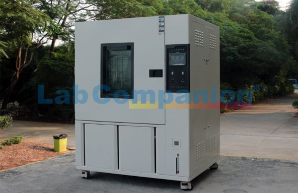
The walk-in constant temperature laboratory is a crucial facility in modern scientific research and industrial experimentation. Its core principle involves maintaining a stable and reproducible experimental environment by precisely controlling temperature and environmental conditions. These laboratories typically use efficient cooling and heating systems, along with advanced temperature sensors and automatic control systems, to ensure precise temperature regulation.
In the walk-in constant temperature laboratory, temperature changes are strictly controlled within a set range. For instance, the typical operating range is from-20℃ to +60℃, which provides excellent conditions for studying the physical and chemical properties of materials. Conducting experiments in such an environment allows researchers to avoid external temperature fluctuations, ensuring more reliable and comparable results. Additionally, the walk-in design offers experimenters greater flexibility, making it easier to test large quantities or complex equipment.
In addition to temperature control, constant temperature laboratories can also regulate humidity, airflow, and other environmental factors to meet the needs of various experiments. For instance, in biological experiments, controlling humidity is equally important, as both excessively high and low humidity levels can affect biological samples. Therefore, these laboratories are typically equipped with humidity monitoring and control systems, using humidifiers or dehumidifiers to precisely manage the indoor air humidity, ensuring the reliability and consistency of experimental conditions.
Furthermore, the structural design of the walk-in constant temperature laboratory takes into account both safety and ergonomics. The equipment is meticulously arranged to allow laboratory personnel to move freely within the space, facilitating smooth experimental operations. In more advanced designs, airtight doors and isolation walls are also incorporated to ensure the independence of the experimental environment, minimizing external influences.
In summary, a walk-in constant temperature laboratory is not just a physical space; it serves as a bridge for scientific exploration. It aids researchers in investigating the performance and reaction mechanisms of materials under various complex environmental conditions, thereby driving the continuous advancement of science and technology. Whether in the development of new materials, drug testing, or climate change research, the constant temperature laboratory plays a crucial role, becoming a sacred experimental haven in the hearts of researchers.
When operating a constant temperature and humidity test chamber, it is important to be aware of potential issues during the process and ensure proper operation. Improper handling can easily lead to equipment malfunctions. However, over time, some faults will inevitably occur. In this article, we will discuss several common faults and their solutions.
Fault: If the temperature does not reach the set value during high-temperature testing, the first step is to check the electrical system and troubleshoot each component. If the temperature in the constant temperature and humidity test chamber rises too slowly, check the air circulation system to ensure the adjustment damper is functioning properly. If the temperature rises too quickly, adjust the PID settings. If the temperature rises too quickly and triggers the over-temperature protection, the controller may be faulty; in this case, replace the control panel or solid-state relay.
Fault: If the constant temperature and humidity test chamber fails to meet the low-temperature test requirements, investigate whether the temperature drops very slowly or if it stabilizes at a certain point before rising again. If the temperature drops very slowly, check if the chamber was dried before the low-temperature test to maintain dryness. Ensure the samples are not placed too densely to prevent inadequate air circulation. After ruling out these issues, consider whether the refrigeration system is malfunctioning; in such cases, seek professional repair from the manufacturer.
Fault: If the constant temperature and humidity test chamber malfunctions during operation, with the control panel displaying a fault message and an audio alarm, the operator can refer to the troubleshooting section of the equipment's user manual to identify the type of fault. Professional maintenance personnel should then perform the necessary repairs to ensure the test proceeds smoothly. Other environmental experimental equipment will have other conditions in use, which need to be dealt with according to the current situation.
One reason 1. Because the temperature of the constant temperature and humidity test chamber cannot be maintained, observe whether the refrigeration compressor can start when the test chamber is running, and whether the compressor can start when the environmental test equipment is running, indicating that the circuit from the main power supply to each compressor is normal and the electrical system has no problem.
2. There is no fault in the electrical system. Continue to check the refrigeration system. First, check whether the exhaust and suction pressure of the low temperature (R23) compressor of the two sets of refrigeration units are lower than the normal value, and whether the suction pressure is in the vacuum state, indicating that the refrigeration dose of the main refrigeration unit is insufficient.
3. Touch the exhaust pipe and suction pipe of the R23 compressor with your hand, and find that the temperature of the exhaust pipe is not high, and the temperature of the suction pipe is not low (no frost), which also indicates that the R23 refrigerant in the host is insufficient.
Another reason: 1. The cause of the failure has not been determined, and further confirmation is made in combination with the control process of the constant temperature and humidity test chamber. The test chamber has two sets of refrigeration units.
One is the main unit, and the other is the auxiliary unit. When the cooling rate is high, both units operate simultaneously at the beginning of the temperature maintenance phase. Once the temperature stabilizes, the auxiliary unit stops, and the main unit maintains the temperature. If the R23 refrigerant leaks from the main unit, its cooling efficiency will be significantly reduced. During the cooling process, both units operate simultaneously, ensuring stable temperatures and a gradual decrease in cooling rate. In the insulation phase, if the auxiliary unit stops, the main unit loses its cooling function, causing the air inside the test chamber to rise slowly. When the temperature reaches a certain level, the control system activates the auxiliary unit to cool down, after which the auxiliary unit stops again. The cause of the production failure has been identified as a low-temperature (R23) refrigerant leak from the main unit. Upon checking the refrigeration system for leaks, a crack was found on the valve stem of the hot gas bypass solenoid valve, measuring about 1cm in length. After replacing the solenoid valve and recharging the system with refrigerant, the system returned to normal operation. This analysis shows that the fault diagnosis follows a step-by-step approach, starting from the 'external' aspects and moving inward, then focusing on 'electricity' and finally on 'cooling.' A thorough understanding of the test chamber's principles and operational processes is essential for accurate fault diagnosis.
1. The condenser (or radiator) of the refrigeration unit in the cold and heat shock test chamber should be regularly maintained to ensure it remains clean. Dust that adheres to the condenser can cause the compressor's high-pressure switch to trip, leading to false alarms. The condenser should be cleaned monthly using a vacuum cleaner to remove dust from the condenser's cooling mesh, or after turning on the machine, use a hard-bristled brush to clean it, or blow away the dust with a high-pressure air nozzle.
2. When opening or closing the door or taking the test object from the furnace, do not let the item touch the rubber edge on the door to prevent the rubber edge from being damaged and shortened life.
3. Keep the ground around and under the fuselage clean at all times to avoid accidents and performance degradation caused by large amounts of dust being sucked into the unit.
4. The freezing system of the cold and hot shock test chamber is the core of this machine. Please inspect all copper tubes for leakage and snow conditions every half a year, as well as all nozzles and welding joints. If there is oil leakage, please inform the company or deal with it directly.
5. The large current contact of the distribution panel should be cleaned and repaired at least once a year in the distribution room. The loosening of the contact will make the whole equipment work in a risky state. At best, it will burn out the components, and at worst, it will cause fire, alarm and personal injury. When cleaning, use a vacuum cleaner to remove the dust in the room.
6. Do not adjust the setting value of the two over-temperature protectors in the power distribution box of the cold and hot shock test chamber casually. It has been adjusted at the factory. This protective switch is used to protect the heating tube from empty burning and alarm. The setting point = temperature setting point 20℃~30℃.
7. Cold and hot shock test chamber When the test product is taken when the time arrives, it must be in the off state and the staff must wear dry, anti-electricity and temperature-resistant gloves to take and put the product.
8. Clean and maintain the inside and outside of the cold and heat shock test chamber. 9. Before operating the cold and heat shock test chamber, remove any internal impurities. 10. The electrical distribution room should be cleaned at least once a year. When cleaning, use a vacuum cleaner to remove dust. The exterior of the chamber must be cleaned at least once a year, using soapy water for wiping.
This device differs from ordinary equipment, so the installation site must meet the following special requirements:
The site must have ample space for the test equipment and sufficient maintenance area.
The laboratory should be equipped with a water supply system.
The installation site should have ideal drainage facilities, such as ditches and outlets.
The power supply for the device should have a good grounding system and a waterproof base and cover to prevent electrical leakage or electric shock due to water splashing onto the power source.
The height of the installation site should allow the device to operate normally and facilitate future maintenance and repairs after installation.
The annual temperature at the installation site should be maintained between 5-32℃, with a relative humidity not exceeding 85%, and there should be adequate ventilation.
The installation should be in a dust-free environment.
The environmental temperature at the installation site should avoid sudden changes.
The installation should be on a level surface (using a level to ensure it is level).
The installation should be in a location away from direct sunlight.
The installation should be far from flammable materials, explosive materials, and high-temperature heat sources.
It is best not to install other equipment in the laboratory to prevent moisture-induced corrosion.
Water source: municipal tap water。
Eight key points of choosing high and low temperature test chamber:
1.No matter whether it is selected for high and low temperature test chamber or other test equipment, it should meet the temperature conditions specified in the test requirements;
2.To ensure the uniformity of temperature in the test chamber, forced air circulation or non-forced air circulation mode can be selected according to the heat dissipation of samples;
3.The heating or cooling system of the high and low temperature test chamber shall have no effect on the samples;
4.The test chamber should be convenient for the relevant sample rack to place samples, and the sample rack will not change its mechanical properties due to high and low temperature changes;
5. High and low temperature test chamber should have protective measures. For example: there are observation window and lighting, power disconnection, over-temperature protection, various alarm devices;
6. Whether there is remote monitoring function according to customer requirements;
7. The test chamber must be equipped with automatic counter, indicator light and recording equipment, automatic shutdown and other instrument devices when carrying out the cyclic test, and it must have good recording and display functions;
8.According to the sample temperature, there are two measurement methods: upper wind and lower wind sensor temperature. The position and control mode of temperature and humidity control sensor in the high and low temperature test chamber can be selected according to the customer's product test requirements to select the appropriate equipment.
The high and low temperature, humidity, and heat test chamber employs a balanced temperature and humidity control method to achieve precise environmental conditions. It features stable and balanced heating and humidification capabilities, enabling high-precision temperature and humidity control at high temperatures. Equipped with an intelligent temperature regulator, the chamber uses a color LCD touch screen for temperature and humidity settings, allowing for various complex program settings. The program settings are set through a dialogue interface, making the operation simple and quick. The refrigeration circuit automatically selects the appropriate cooling mode based on the set temperature, enabling direct cooling and temperature reduction in high-temperature conditions. The base is constructed from welded channel steel into a grid frame, ensuring it can support the weight of the chamber and personnel under horizontal conditions without causing unevenness or cracking on the bottom surface. The chamber is divided into six surfaces and a double or single-opening door. The inner shell is made of stainless steel plate, while the outer shell is made of color-coated steel plate. The insulation medium is polyurethane rigid foam, which is lightweight, durable, and resistant to impact. The door is also made of color-coated steel plate, with handles designed for both internal and external opening, allowing test personnel to freely open the door from inside the enclosed chamber. This test chamber can record and trace the entire testing process, with each motor equipped with overcurrent protection and short-circuit protection for the heater, ensuring high reliability during operation. It is equipped with USB interfaces and Ethernet communication functions, meeting customers' diverse needs for communication and software expansion. The popular refrigeration control mode reduces energy consumption by 30% compared to the traditional heating balance control mode, saving energy and electricity. The chamber typically consists of a protective structure, air duct system, control system, and indoor testing framework. To better ensure the temperature reduction rate and temperature specifications of the high and low temperature humidity test chamber, a cascade refrigeration unit, which uses imported refrigeration compressors, is selected. This type of refrigeration unit offers advantages such as effective coordination, high reliability, and easy application and maintenance. When using this system, certain details should not be overlooked. What are these details?
1. Strictly abide by the system operation rules to avoid others violating the system operation rules.
2. Non-technical personnel are not allowed to disassemble and repair this machine. If disassembly and repair are required, the operation shall be carried out under the condition of ensuring power off and accompanied by personnel for supervision to avoid accidents.
3. When opening or closing the door or taking or putting the test object out of the test chamber, do not let the test object contact with the rubber edge of the door or the edge of the box to prevent the rubber edge from being worn.
4, the surrounding ground should be kept clean at any time, so as not to suck a lot of dust into the unit to deteriorate working conditions and reduce performance.
5. Attention should be paid to protection during use, and it should not be collided with sharp or blunt objects. The test products placed in the laboratory should be kept at a certain distance from the suction and exhaust air outlets of the air conditioning channel to avoid hindering the air circulation.
6. Prolonged inactivity can reduce the system's effective lifespan, so it should be powered on and operated at least once every 10 days. Avoid frequent short-term use of the system. After each operation, the system should not be restarted more than 5 times per hour, with each start-stop interval being at least 3 minutes. Do not open the door when it is cold to prevent damage to the door seal.
7. After each test, set the temperature near the ambient temperature, work for about 30 minutes, then cut off the power supply, and wipe clean the inner wall of the working room.
8. Regular cleaning of the evaporator (dehumidifier): Due to the different cleanliness levels of the samples, a lot of dust and other small particles will be condensed on the evaporator (dehumidifier) under the action of forced air circulation, so it should be cleaned regularly.
9. The condenser should be maintained regularly and kept clean. Dust sticking to the condenser will make the compressor dissipate heat poorly, resulting in high pressure switch jumping and generating false alarm. The condenser should be maintained regularly.
10. Regularly clean the humidifier to prevent scale buildup, which can reduce its efficiency and lifespan and cause blockages in the water supply lines. To clean it, remove the evaporator panel from the working chamber, use a soft brush to scrub the humidifier, rinse with clean water, and drain promptly. 11. Regularly check the test cloth of the wet bulb. If the surface becomes dirty or hard, replace it to ensure the accuracy of the humidity sensor's readings. The test cloth should be replaced every three months. When replacing it, first clean the water collection head, wipe the temperature sensor clean with a clean cloth, and then replace the test cloth. Ensure your hands are clean when replacing the new test cloth.
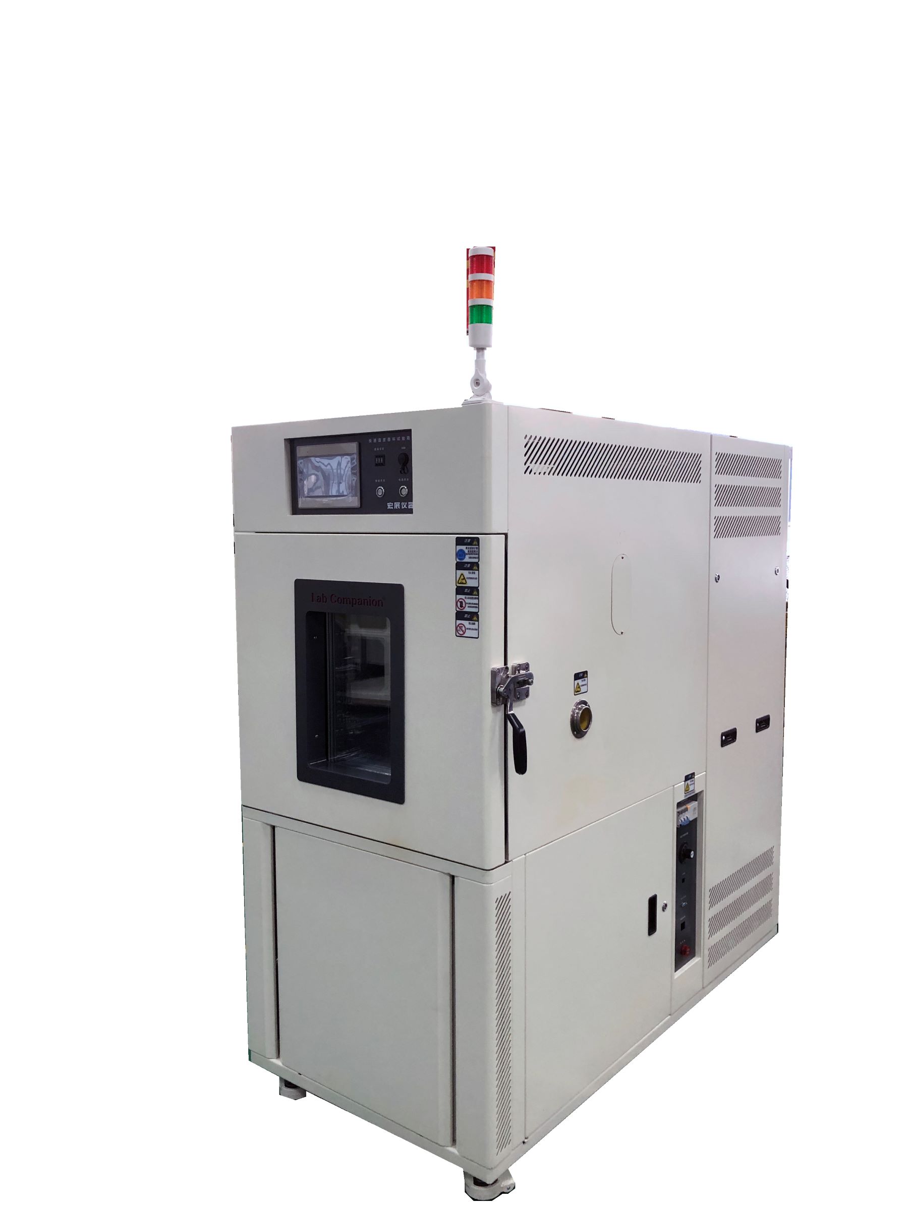
The rapid temperature change test chamber is suitable for aerospace products, information and electronic instruments, materials, electrical and electronic products, and various electronic components to test the performance indicators of products under the condition of rapid temperature change.
Characteristics of the rapid temperature change test chamber: 1. The chamber is designed with advanced and rational structure, featuring internationally advanced products and functional components that meet long-term, stable, safe, and reliable production needs. It meets the processing and production requirements for these applications, is user-friendly in terms of operation, maintenance, and use, has a long service life, an attractive design, and a user-friendly interface that simplifies and enhances the user's operational and monitoring experience.
2. The main components of the equipment are selected from high-quality products of well-known international brands to ensure the quality and performance of the whole machine.
3. Perfect equipment performance and easy to operate man-machine dialogue function.
4. Have independent intellectual property rights and design patents and master the core technology of environmental test chamber.
5. The control instrument adopts the original Japanese imported "Youyikong" UMC1200, which can be monitored remotely.
6. The refrigeration system adopts the original French Taikang compressor unit, and is equipped with condensate water tray.
7. Core electrical components are all imported well-known brands such as Schneider.
8. Follow the advanced design concept of foreign environmental test equipment, and separate water and electricity.
9. Shallow tank humidification, novel and unique, drawer water adding method, super large tank design.
10. The bottom of the studio adopts drainage groove design to prevent steam condensation and maximize the protection of test workpiece.
11. The lighting system adopts philips kit, and the observation window adopts funnel-shaped design to provide a wider field of view.
12. Unique leakage protection design for safer operation.
High and low temperature humidity test chamber plays an important role in many industries due to its powerful environmental simulation ability. The following is an overview of its main application industries:
❖ Aerospace is used to test the performance of aircraft, satellite, rocket and other aerospace components and materials under extreme temperature and humidity conditions.
❖ Test the stability and reliability of electronic components, circuit boards, displays, batteries and other electronic products in high temperature, low temperature and humidity environment.
❖ Evaluate the durability of automotive components such as engine parts, electronic control systems, tires, and coatings in harsh environments.
❖ Defense and military use environmental adaptability tests of military equipment and weapon systems to ensure their normal operation under a variety of climatic conditions.
❖ Material science research on the heat resistance, cold resistance and moisture resistance of new materials, as well as their physical and chemical properties under different environmental conditions.
❖ Energy and environmental assessment of the environmental adaptability and weather resistance of new energy products such as solar panels and energy storage equipment.
❖ Transportation test of the performance of components of vehicles, ships, aircraft and other transportation vehicles in extreme environments.
❖ Biomedical testing of the stability and effectiveness of medical devices and drugs under changes in temperature and humidity.
❖ Quality inspection is used for environmental testing and certification of products in the product quality control center.
High and low temperature humidity test chamber helps enterprises and institutions in the above industries to ensure that their products can operate normally in the expected use environment by simulating various extreme conditions that may be encountered in the natural environment, so as to improve the market competitiveness of products.
A high and low temperature humidity test chamber is a device used to test the performance of products in high temperature, low temperature or humid and hot environments. It is widely used in the testing of aerospace products, information electronic instruments and meters, materials, electrical appliances, electronic products, and various electronic components.
Basic Working Principle:
❖ Box structure: usually made of stainless steel or other corrosion-resistant materials, the internal space is used to place the sample under test, and the external control panel and display are installed.
❖ Temperature and humidity control system: including heater, refrigeration system (single stage, double stage or stacked refrigeration), humidification and dehumidification device, as well as sensors and microprocessors to ensure that the temperature and humidity in the box is precisely controllable.
❖ Air circulation system: built-in fans promote air circulation in the box to ensure uniform temperature and humidity distribution.
❖ Control system: microcomputer or PLC controller is used. Users can set the required temperature, humidity and test time through the operation interface, and the system will automatically execute and maintain the set conditions.
Lab Companion was established on May 4, 2005, and is a national high-tech enterprise headquartered in Dongguan, Guangdong Province. The company has two major R&D and manufacturing facilities in Dongguan and Kunshan, covering a total area of 10,000 square meters. It produces approximately 2,000 environmental test equipment units annually. The company also operates sales and maintenance service centers in Beijing, Shanghai, Wuhan, Chengdu, Chongqing, Xi 'an, and Hong Kong. Hongzhan has always been dedicated to the technology of environmental test equipment, continuously striving for excellence to create reliability that meets international standards. Its customers span various industries, including electronics, semiconductors, optoelectronics, communications, aerospace, machinery, laboratories, and automotive. From product development to after-sales service, every step is guided by the customer's perspective and needs.
Introduction
Reliability testing is a critical process in the development and production of equipment, ensuring that devices meet specified performance standards under expected operating conditions. Depending on the test environment, reliability testing can be classified into laboratory testing and field testing. Laboratory reliability tests are conducted under controlled conditions, which may or may not simulate real-world scenarios, whereas field reliability tests are performed in actual operational environments.
Based on the objectives and stages of product development, reliability testing can be further divided into:
Reliability Engineering Tests (including Environmental Stress Screening (ESS) and Reliability Growth Testing) – aimed at identifying and eliminating faults, typically conducted during the development phase.
Reliability Statistical Tests (including Reliability Verification Tests and Reliability Measurement Tests) – used to validate whether a product meets reliability requirements or to estimate its reliability metrics, usually performed during development and production.
This article focuses on Reliability Statistical Testing, covering test procedures, methodologies, performance monitoring, fault handling, and reliability metric calculations.
1. General Test Plan and Requirements
(1) Pre-Test Preparation
Before conducting reliability testing, a Reliability Test Plan must be developed, leveraging existing test data to avoid redundancy. Key preparatory steps include:
Equipment Readiness: Ensure that the device under test (DUT), test equipment, and auxiliary instruments are properly configured and calibrated.
Environmental Stress Screening (ESS): The DUT should undergo ESS to eliminate early-life failures.
Test Review: A pre-test review should confirm that all conditions are met for a valid test.
(2) Comprehensive Environmental Test Conditions
The test environment should simulate real-world operational stresses, including:
Stress Combination: Sequential simulation of major stresses encountered in actual use.
Operating Conditions: The DUT should operate under typical workload and environmental conditions.
Standard Compliance: Test conditions should align with technical standards or contractual requirements.
(3) Statistical Test Plans and Selection
Two primary test plans are defined:
Fixed-Time Truncated Test Plan: Suitable when precise test duration and cost estimation are required.
Sequential Truncated Test Plan: Preferred when the producer’s and consumer’s risks (10%–20%) are acceptable, especially for high- or low-reliability devices or when sample sizes are small.
Sample Selection:
The DUT must be randomly selected from a batch produced under identical design and manufacturing conditions.
A minimum of two samples is recommended, though a single sample may be allowed if fewer than three units are available.
2. Types of Reliability Statistical Tests
(1) Reliability Qualification Test
Purpose: To verify whether the design meets specified reliability requirements.
Key Aspects:
Conducted under simulated operational conditions.
Requires representative samples of the approved technical configuration.
Includes test condition determination, fault classification, and pass/fail criteria.
(2) Reliability Acceptance Test
Purpose: To ensure that mass-produced devices meet reliability standards before delivery.
Key Aspects:
Performed on randomly selected samples from production batches.
Uses the same environmental conditions as qualification testing.
Includes batch acceptance/rejection criteria based on test results.
(3) Reliability Measurement Test
Purpose: To estimate reliability metrics such as failure rate (λ), mean time between failures (MTBF), and mean time to failure (MTTF).
Key Aspects:
No predefined truncation time; reliability can be estimated at any stage.
Statistical methods are used to compute point estimates and confidence intervals.
(4) Reliability Assurance Test
Purpose: An alternative to acceptance testing for highly reliable or mature products where conventional testing is impractical.
Key Aspects:
Conducted after ESS.
Focuses on fault-free operation duration (t).
Requires agreement between the manufacturer and customer.
Conclusion
Reliability environmental testing is essential for ensuring product durability and performance. By implementing structured test plans—whether qualification, acceptance, measurement, or assurance testing—manufacturers can validate reliability metrics, optimize designs, and deliver high-quality products.
Environmental reliability testing can be achieved through environmental test chambers, which simulate real-world conditions to evaluate product performance, significantly reducing testing time and improving efficiency.
Lab-Companion has over 20 years of expertise in manufacturing environmental test equipment. With extensive practical experience and on-site installation support, we help customers overcome real-world challenges in testing applications.
This article analyzes the system architecture and technical characteristics of rapid temperature change test chambers, by systematically studying the technical parameters and functional design of key components, it provides theoretical guidance for equipment selection and process optimization.
1.Technical Principles and System Architecture
Rapid temperature change test chambers operate based on thermodynamic transfer principles, achieving nonlinear temperature gradient variations through high-precision temperature control systems. Typical equipment can attain temperature change rates ≥15℃/min within a range of -70℃ to +150℃. The system comprises four core modules:
(1) Heat exchange system: Multi-stage cascade refrigeration structure
(2) Air circulation system: Adjustable vertical/horizontal airflow guidance
(3) Intelligent control system: Multivariable PID algorithm
(4) Safety protection system: Triple interlock protection mechanism
2.Analysis of Key Technical Features
2.1 Structural Design Optimization
The chamber adopts modular design with SUS304 stainless steel welding technology. A double-layer Low-E glass observation window achieves >98% thermal resistance. The CFD-optimized drainage channel design reduces steam condensation to <0.5 mL/h.
2.2 Intelligent Control System
Equipped with Japan-made YUDEN UMC1200 controller.
2.3 Refrigeration System Innovation
Incorporates French Tecumseh hermetic scroll compressors with R404A/R23 refrigerants.
3.Safety and Reliability Design
3.1 Electrical Safety System
Complies with IEC 61010-1 CLASS 3
Schneider Electric components with full-circuit isolation
Grounding resistance <0.1Ω
Overcurrent protection response <0.1s
3.2 Multi-level Protection
Triple-channel PT100 temperature monitoring
Dual pressure switches
Dry-burn humidity protection
Emergency pressure relief valve
4.Technological Applications
(1) Aerospace: Thermal-vacuum testing for satellite components
(2) New energy vehicles: Battery pack thermal shock tests
(3) Microelectronics: Chip package reliability verification
(4) Materials science: Composite interlayer thermal stress analysis
5.Technological Trends
(1) Multi-stress coupling tests: Temperature-vibration-humidity simulation
(2) Digital twin integration: Virtual system modeling
(3) AI-driven parameter optimization: Machine learning-based curve tuning
(4) Energy efficiency: 40%+ heat recovery rate
Conclusion: With increasing reliability requirements in advanced industries, future development will emphasize intelligent operation, high precision, and multidimensional environmental simulation. Subsequent research should focus on integrating equipment with product failure mechanism models to advance environmental testing from verification to predictive analysis.
Click to view related products.
Lab Companion, your trusted brand.


 Get A Quote


 IPv6 network supported