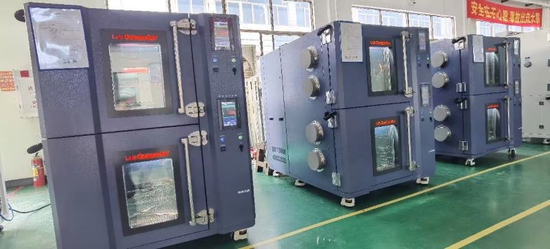
The High and Low Temperature Humid Test Chambers is the main equipment in temperature and humidity environment testing, mainly used for evaluating the temperature and humidity tolerance of products, so as to ensure that our products can work and operate normally under any environmental conditions. However, if the temperature uniformity exceeds the allowable deviation range during environmental testing in the Chambers, the data obtained from the test is unreliable and cannot be used as the ultimate tolerance for high and low temperature testing of materials. So what are the reasons that can cause temperature uniformity to exceed the allowable deviation range?
1. The differences test objects in the High and Low Temperature Humid Test Chamber: If test samples that to a great extent affect the overall camber’s internal heat convection, it will inevitably affect the uniformity of internal sample’s temperature. For example, if LED lighting products are test, the products themselves emit light and heat, becoming a thermal load, which will has a significant impact on temperature uniformity.
2. The volume of the tested object: If the volume of the test object is too large, or the placing position in the chamber is inappropriate, it will obstruct the air convection inside and also cause significant temperature uniformity deviation. For Placing the test product next to the air duct seriously affects the circulation of air, and of course, the uniformity of temperature will be greatly affected.
3. The internal structure design of the chamber: This aspect is mainly reflected in sheet metal design and processing, such as the design of air ducts, the placement of heating pipes, and the size of fan power. All of these will affect the temperature uniformity inside the camber.
4. Design of the camber’s inner wall: Due to the different structures about the inner wall of the test chamber, the temperature of the inner wall will also be uneven, which will affect the heat convection inside the working chamber and cause deviation in the internal temperature uniformity.
5. The six sides of the camber have uneven heat dissipation: Due to the different heat transfer coefficients on the front, back, left, right, top, and bottom surfaces of the camber’s wall, some sides have threading holes, others have testing holes, etc., which will cause local heat dissipation and transfer, resulting in uneven temperature distribution of the camber and uneven radiative convective heat transfer on the wall, final affecting temperature uniformity.
6. The leakproofness of camber’s door: The sealing of the camber and door is not strict, for example, the sealing strip is not customized and has seams between door and wall, the door will leaks the air, which is going to affects the temperature uniformity of the hole camber.
In summary, those may the culprit affected the temperature uniformity inside the test chamber, we suggest that you can investigate from these aspects one by one, which will surely solve your confusion and difficulties.
Why Should You Evacuate Before Heating in a Vacuum Drying Oven?
1) Protect the Vacuum Pump:
If you heat the oven before evacuating, the heated air will be drawn out by the vacuum pump. This process transfers heat to the pump, potentially causing it to overheat. Overheating can reduce the efficiency of the vacuum pump and may even damage it.
2) Preventing Damage to the Vacuum Gauge:
If heating the oven first, heated air would directed toward the Vacuum Gauge and cause this instrument to overheat. If the temperature exceeds the gauge's operational limits, it may lead to inaccurate readings or permanent damage.
3)Avoiding Safety Hazards:
The tested material is placed in the vacuum chamber that can remove extracted gases from the material. If the tested material is heated first, the gas will expand when it encounters heat. Due to the excellent sealing of the vacuum chamber, the immense pressure generated by the expanding gas could cause the tempered glass of the observation window to shatter.
The correct procedure is to evacuate air first and then heat. If the vacuum level drops after reaching the desired temperature, you can briefly re-evacuate. This method helps extend the lifespan of the equipment.
Conclusion:
To ensure safety, maintain equipment efficiency, and prolong the lifespan of vacuum drying oven, always follow the correct procedure: evacuate air first, then heat. This simple step can prevent potential hazards and costly damages.
We have cooperated with the German company - Froilabo and brought in the dragon because it can control the temperature like the dragon in the fantasy story. Dragon, A high-precision temperature forcing system that can rapidly heat and cool samples to determine their durability and resistance against precise thermal environments.
In this blog discover what a temperature forcing system is, and how our Dragon can help you by providing precise thermal testing for a wide variety of applications.
Key points:
A temperature forcing system is used to test a samples resilience and durability under different temperature conditions.
Thermal testing is crucial to ensure products are safe to use and meet required safety standards and regulations.
A temperature forcing system is suitable for a wide variety of applications, which includes heating electronic components, electronic characterization, and performing climatic simulations.
Dragon is the perfect solution for all your thermal testing needs, and features high performance and accuracy at all steps of analysis.
What is a temperature forcing system?
A temperature forcing system is used to evaluate a samples performance under different temperature conditions. By subjecting samples to rapid temperature changes, you can test them for their resilience and durability.
These systems are crucial for several reasons:
Improve safety: By subjecting devices to rapid temperature changes, you can ensure they meet your required safety standards and regulations.
Efficient product development: By testing different components early in the design and development phase, you can identify any potential issues early and rectify it quickly.
Assess reliability and performance: By testing your samples performance you can ensure your devices can withstand extreme temperatures.
How does a temperature forcing system work?
A temperature forcing system works by using a direct temperature-controlled stream of hot or cold air to provide a precise thermal environment for your samples. The Dragon provides a temperature range from -70oC to +250oC, to ensure sample function and viability at a wide range of temperatures.
Do I need a temperature forcing system?
Anyone who requires precise thermal testing would benefit from a temperature forcing system, and with Dragon it couldn’t be easier. All you have to do is create a method and Dragon does the rest.
In many industries, it’s essential to characterize and verify product performance when subjected to temperature variations. Dragon provides the perfect solution – our versatile and stable thermal unit is perfect for a wide range of applications.
Applications of the Dragon include:
Heating electronic components
Heating printed circuit boards
Performing climatic simulations
Electronic characterization
Temperature cycling and targeted freezing applications
Discover the Dragon, the one stop solution for all your thermal testing needs:
Excellent temperature stability: Delivering precision at every step of your testing, with a temperature range from -70oC to +250o
Rapid temperature changes: Our Dragon effortlessly shifts from -55oC to +125oC in a matter of seconds (something even the mystical dragon can’t yet achieve)
Digital connections: Connect your computer to your Dragon for simple method creation and run monitoring.
Easy manoeuvring: It can still move with ease using the guide handle and 4 wheels to easily transport to your desired location.
Adaptable to your needs: Our versatile product contains an adjustable airflow between 2.2 l/sec and 8.4 l/sec and three different working methods – manual, automatic and programmable.
Compliance at every step: Dragon has been tested in accordance to and complies with the European norm in force: EN60068-3-11.
Learn more about the dragon by visiting our dedicated Dragon product page.
Condition one: environmental condition
1. Temperature: 15 ℃~35 ℃;
2. Relative humidity: not exceeding 85%;
3. Atmospheric pressure: 80kPa~106kPa
4. There is no strong vibration or corrosive gas around;
5. No direct sunlight exposure or direct radiation from other cold or heat sources;
6. There is no strong airflow around, and when the surrounding air needs to be forced to flow, the airflow should not be directly blown onto the equipment.
7.No magnetic field surrounding of the test chamber that may interference control circuit.
8.There is no high concentration of dust and corrosive substances around.
Condition two: Power supply condition
1. AC Voltage: 220V ± 22V or 380V ± 38V;
2. Frequency: 50Hz ± 0.5Hz.
Usage Conditions three: Water Supply Conditions
It is recommended to use tap water or circulating water that meets the following conditions:
1.Water Temperature: Not exceeding 30℃;
2.Water Pressure: 0.1MPa to 0.3MPa;
3.Water Quality: Complies with industrial water standards.
Usage Conditions four: load for test chamber
The test chamber load must simultaneously meet the following conditions:
1. Total Mass of Load: The mass of the load per cubic meter of workspace volume should not exceed 80 kg;
2. Total Volume of Load: The total volume of the load should not exceed 1/5 of the workspace volume;
3. Load Placement: On any cross-section perpendicular to the main airflow direction, the total area of the load should not exceed 1/3 of the workspace cross-sectional area. The load must not obstruct airflow.
The High-Low Temperature and Low Pressure Test Chamber is an experimental instrument for simulating the storage, operation, and transportation reliability on high-altitude, plateau areas climates in the national defense industry, aerospace industry automation components, automotive components, electronic and electrical components, plastics, chemical industry, food industry, pharmaceutical industry, and related products under the single or simultaneous action of high/low temperature and low pressure. It can also conduct electrical performance parameters on test specimens when powered on at the same time.
The High-Low Temperature and Low Pressure Test Chamber can perform high temperature, low temperature, altitude (not higher than 30000 meters or 45000 meters above sea level), high/low temperature cycle tests, and temperature altitude comprehensive tests on products (whole machine), components, and materials. During high and low temperature tests, this chamber can be used for testing heat dissipation samples and non heat dissipation samples. For the heat dissipation sample, its heat dissipation power cannot exceed the cooling capacity of the chamber, as the cooling capacity is a dynamic value that varies with temperature points.
Main materials of our equipment:
Adopting a bipolar rotary vane vacuum pump with high ultimate vacuum degree - ensuring efficient and stable operation of the equipment throughout its entire working range;
High strength and high reliability structural design - ensuring the high reliability of the equipment;
The inside chamber material is SUS304 stainless steel - with strong corrosion resistance, cold and hot fatigue function, long service life;
High density polyurethane foam insulation material - ensuring minimal heat loss;
Surface spraying treatment - ensuring the long-lasting anti-corrosion function and appearance life of the equipment;
High strength heat-resistant silicone rubber sealing strip - ensures high sealing performance of equipment doors;
Multiple optional functions (such as test holes, recorders, water purification systems, etc.) - ensuring users have multiple functions and testing needs;
Large area electric anti frost observation window and concealed lighting - providing good observation effect;
Environmentally friendly refrigerants - ensure that equipment better meets your environmental protection requirements;
*Customizable size/usage indicators/various optional features according to your requirements.
Main functions of our equipment:
Temperature control: It can achieve temperature constant control and program control;
The full process data recorder (optional function) can achieve full process recording and traceability of the experimental process;
Each motor is equipped with overcurrent (overheating) protection/heater short-circuit protection to ensure high reliability of air flow and heating during equipment operation;
USB interface and Ethernet communication function enable the device's communication and software expansion functions to meet various customer needs;
Adopting the internationally popular cooling control mode, the compressor cooling power can be automatically adjusted from 0% to 100%, reducing energy consumption by 30% compared to the traditional heating balance temperature control mode;
The key components of refrigeration and electrical control are all made of internationally renowned brand products, which improves and ensures the overall quality of the equipment.
Walk-in Temperature Test Chamber is a large laboratory that admit operator to walk in it, primarily used for environmental testing. It is commonly used for testing large parts, semi-finished products, and finished products to simulate real-world environmental temperatures, and is widely used in industries such as electrical engineering, electrical appliances, instruments, electronics, security, communication, sensors, automation, industrial control, precision machinery, etc. The Walk-in Temperature Test Chamber is equipped with a φ 50mm test hole with a plug on the side of the box. The plug material is low foaming silicone rubber, which can withstand high and low temperatures and has insulation effect. The heater adopts a porcelain frame nickel chromium wire electric heater, which has low thermal inertia and long service life. The instrument outputs a controllable pulse duty cycle PID signal, which is controlled by a solid-state relay to make the control smoother and more reliable.
Performance and characteristics of Walk-in Temperature Test Chamber:
1.It has an extremely wide temperature and humidity control range, which can meet various needs for users. By adopting a unique balanced temperature and humidity control method, a safe and precise temperature and humidity environment can be achieved. It has stable and balanced heating and humidification performance, can achieve high-precision temperature and humidity control.
2.Equipped with intelligent temperature regulators, temperature and humidity are displayed using LED digital display. The high and low temperature damp heat test chamber can be optionally equipped with a temperature and humidity recorder.
3. Automatic selection of refrigeration circuit, the automatic control device has the performance of automatically selecting and operating to the refrigeration circuit according to set value of temperature, realizing direct start of the refrigeration machine and direct cooling under high temperature conditions.
4. The inner door is equipped with a large observation window, which facilitates the observation of the test samples’ experimental status.
5. Equipped with advanced safety and protection devices - residual current circuit breaker, over temperature protector, phase loss protector, and water cut-off protector.
We can customer High and low temperature test chambers, low temperature test chambers, constant temperature and humidity test chambers, high and low temperature damp heat test chambers, high and low temperature alternating damp heat test chambers, salt spray corrosion test chambers. above test chambers can be customized according to your requirements.
Therefore, Walk-in Temperature Test Chamber is suitable for enterprises with high demand on environmental testing and operational space.
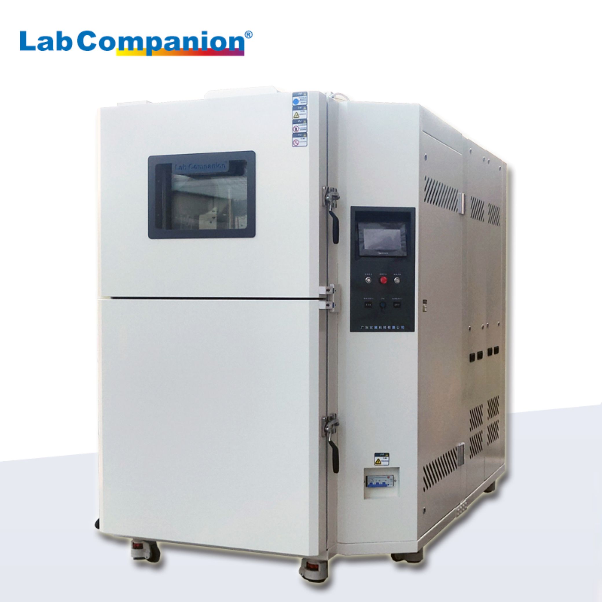
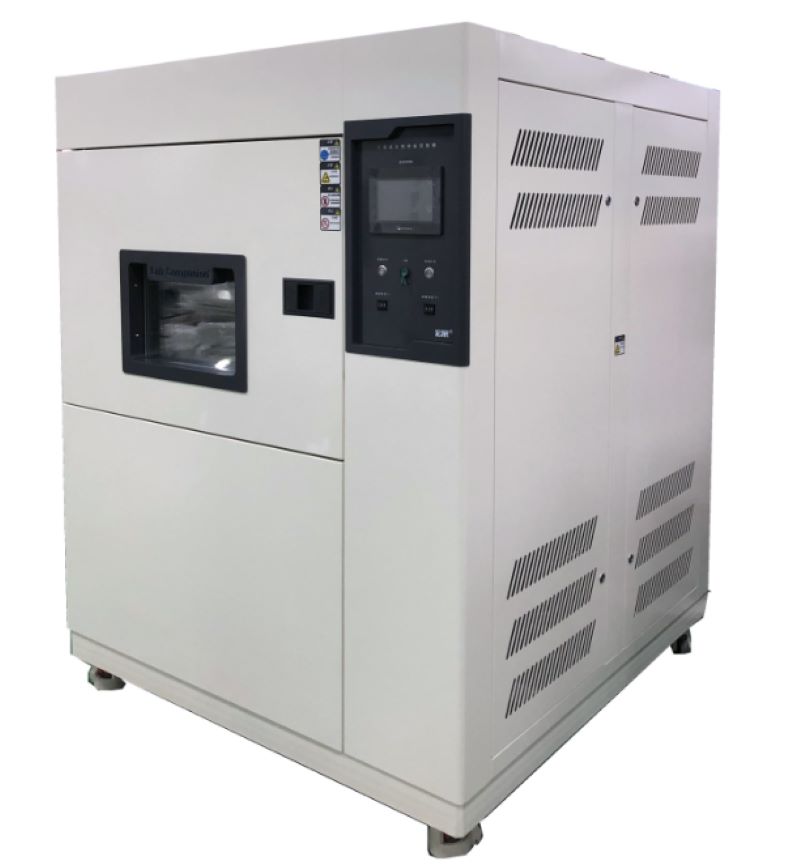
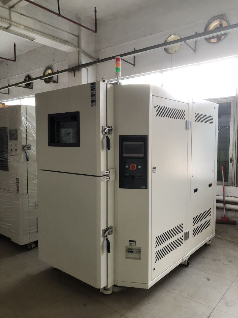
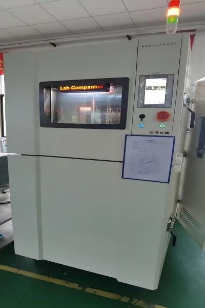
The Thermal Shock Test Chamber is a specialized experimental equipment used to test the performance of materials, electronic components, devices, and other products in extreme temperature conditions. It can simulate environmental changes from extreme cold to extreme heat, through rapid temperature transitions, observing and evaluating the stability and reliability of samples under such harsh conditions. This type of experiment is particularly in manufacturing industrial, electronic devices, and scientific research fields, as many products will facing drastic temperature changes in daily use.
It is extremely important to ensure the normal operation of electronic products in different environments during the designing and manufacturing, especially in the fields of aerospace, automotive electronics, communication equipment, etc. Products must be able to withstand various harsh weather and temperature changes. Through high and low temperature cyclic tests, engineers can reveal potential defects when using, also providing important references for subsequent product improvement and innovation.
The Thermal Shock Test Chamber consists of two main parts: the environmental control system of high and low temperatures. The temperature variation can generally be between -70 ℃ and 150 ℃ in the chamber, and the specific temperature range can be adjusted according to different needs. The experimental process will with multiple cycles, and each cycles contain rapid temperature changes that the sample to intense impacts between high and low temperatures. This type of testing can detect the physical properties of samples, including their tensile strength, elasticity, hardness, and even detect potential issues in thermal fatigue and material aging.
In addition, the design of this testing equipment is also very sophisticated, often equipped with advanced monitoring systems that can record temperature changes and sample reactions in testing process, making the evaluation work more accurate and efficient. With the development of technology, the technology of Thermal Shock Test Chamber is also constantly updated, which not only improves the accuracy and speed of testing, but also enhances the safety and reliability of use.
In summary, Thermal Shock Test Chamber is an indispensable tool in modern material and product research. It provides us with an effective means to ensure that products can always maintain superior performance and stable quality in changing environments. It is an important link in promoting technological progress and industrial development. Through such experiments process, we can gain a deeper understanding of the characteristics and behavior of materials, thereby promoting the birth of safer and more reliable products.
Rechargeable battery, which can be re-active by charging after be used. They are widely used in the fields of environmentally friendly vehicles, power storage, and Dynamic field.
Environmental testing of rechargeable battery is an important means of evaluating their performance under different environmental conditions.
Ⅰ. Testing Purpose
The environmental testing of rechargeable battery aims to simulate various conditions that may be encountered in actual usage environments to evaluate the reliability and performance of the battery. Through testing, it is possible to understand the conditions of working battery under different temperature, humidity, vibration, impact and other conditions, providing scientific basis for the research and development, production and use of battery.
Ⅱ. Testing content
A. Temperature testing
a. High temperature test: Rich a high temperature environment to observe its temperature stability and the risk of thermal runaway.
b. Low temperature testing: Testing the discharge performance, capacity degradation, and low-temperature starting ability of the battery under low temperature conditions.
c. Temperature cycling test: Simulate the temperature changes that the battery may experience in actual use, evaluate its thermal durability and cycle life.
B. Humidity test: Evaluate the battery’s performance, sealing, and corrosion resistance in a humid environments.
C. Vibration testing: Through simulate the battery in the vibration environment that may encounter during transportation, installation, and use, evaluate its structural integrity, electrical connection reliability, and performance stability.
D. Impact testing: Through simulating the battery in unexpected situations such as drops and collisions, and evaluate their impact resistance.
E. External short circuit test: Test the performance of the battery under external short circuit conditions, including risks of thermal runaway and explosion and so on.
Ⅲ. Test standards and specifications
The environmental testing of rechargeable battery should follow relevant testing standards and specifications to ensure the accuracy and comparability of test results. Common testing standards include:
IEC 62133/ IEC 61960、UN 38.3、UL 1642/UL 2580、GB/T 31467、JIS C 8714
Ⅳ. Test equipment
Environmental testing on rechargeable battery requires the professional testing equipment and methods. Common testing equipment includes:
High and low temperature test chamber: Used to simulate different temperature environments.
Humidity test chamber: used to evaluate the performance of battery in humid environments.
Vibration test bench: Simulate vibration environment to evaluate the structural integrity and performance stability of battery.
Impact testing machine: used to simulate impacts in unexpected situations such as drops and collisions.
Ⅴ. Test results and evaluation
After completing the test, it is necessary to analyze and evaluate the test results. Based on test data and standard requirements, determine whether the performance of the battery meets the requirements under different environmental conditions. For undesirable battery, further analysis and corresponding improvement measures should be taken.
In summary, environmental testing of rechargeable battery is an important means to ensure their stable and reliable performance in practical use. Professional testing instruments can provide more professional, safe, scientific and effective experimental results for rechargeable battery testing, greatly reducing the cost of testing and bringing convenience to companies.
Click to check related products.
https://www.lab-companion.com/thermal-shock-test-chamber
https://www.lab-companion.com/temperature-and-humidity-chamber
https://www.lab-companion.com/rapid-temperature-cycling-test-chamber
Solution to Thermal Shock Test chamber Refrigeration System Blocking
Thermal shock test chamber is generally composed of compressor, air conditioning evaporator, cooler and pipe system software. Refrigeration system blockage generally has two kinds of dirty blockage and ice blockage, and oil blockage is relatively rare.
1. Dirty and blocked
When the compressor of thermal shock test chamber is damaged, and there is waste in the refrigeration system, this waste is very easy to block in the capillary or filter device, which is called dirty plugging. Dirty blockage is because there is residue in the refrigeration system (oxygenated skin, copper chips, welding through), when it is circulated with the refrigerant system, it causes blockage at the capillary or filter device.
Dirty blockage removal method: remove the capillary tube, filter device, cooler, air conditioning evaporator with gas cutting, disassemble the carbon molecular sieve in the capillary tube and filter device, clean the cooler and air conditioning evaporator, carry out dry, vacuum packaging, welding, and fill with refrigerant.
2. Ice jam
Ice blockage is caused by water entering the refrigeration system of thermal shock test chamber. Due to its own with a certain amount of moisture, coupled with the maintenance or refrigerant in the whole process of taking time processing regulations are not tight, so that water and gas into the system software. Under the ultra-high pressure effect of the compressor, the refrigerant is changed from a liquid to a vapor state, so that the water is passed into the narrow and long capillary tubes with the refrigerant circulation system. When the moisture content of each kilogram of refrigerant exceeds 20mg, the filter device is saturated with water, and the water can not be filtered out. When the temperature of the capillary inlet and outlet is 0 ° C, the water is converted from the refrigerant and becomes ice, resulting in ice blocking.
Dirty blocking and ice blocking are divided into full and half blocked, the common fault condition is that the air conditioning evaporator is not frosting or frosting is not full, the temperature behind the cooler is high, and the hand drying filter or capillary entrance feels that the temperature is basically the same as the indoor temperature, sometimes less than the indoor temperature, and a lot of steam is sprayed out of the cutting process pipe. After the ice jam occurs, the friction resistance of the compressor exhaust pipe increases, resulting in the compressor overtemperature, the overload protector is working, and the compressor stops running. After about 25 minutes, a part of the ice jam melts, the compressor temperature decreases, the contact point of the temperature controller and the overload protector is closed, and the compressor starts the refrigerator. Therefore, the ice blockage has regularity, and the air conditioning evaporator can see regular frosting and defrosting conditions.
Construction and System Software of Two-zone Thermal Shock Test Chamber
Construction of Two-zone Thermal Shock Test Chamber:
1, Construction mode of environmental test chamber:
Environmental test chamber is composed of a high temperature test chamber located at the upper end, a low temperature test chamber located below, a freezer cabinet located at the back and a home appliance control chamber (system software) located on the right. In this way, the shell occupies a small area, compact structure, beautiful appearance design, the freezer unit is placed in a separate generator chamber body, in order to reduce the vibration and noise of the freezer unit operation on the environmental test chamber harm, in addition to the installation and maintenance of the generator set, the household appliance operation panel is placed on the right panel of the environmental test chamber to facilitate the operation of the actual operation;
2, Shell surface raw materials: cold-rolled plate, surface electrostatic powder spraying solution;
3, The shell cavity raw materials: imported stainless steel plate (SUS304);
4, Thermal insulation material: heat resistant hard plastic polyamine ester foam + foam glass plate;
5, The door: single door, equipped with double silicone rubber sealing and sealing rubber strip heating equipment, under the self-limiting temperature heating zone, to avoid the experiment essence and frost;
6, Test rack: move up and down left and right sliding type stainless steel plate test rack. The pneumatic double-effect cylinder shows a stable and symmetrical driving force. The positioning device of the test rack uses an electromagnetic field triggered limit switch;
7, Cable wire installation hole: the upper end of the test rack and the top of the high temperature test chamber is provided with a telescopic cable threading tube.
Air conditioning system software of two-zone thermal shock test chamber:
1, Gas control method: forced circulation system natural ventilation, balanced temperature control method (BTC). The method refers to the refrigeration unit in the continuous operation of the condition, the automatic control system according to the temperature point set according to the PID automatic and operational output results to manipulate the electric heater's heart output, the ultimate UI will exceed this stable balance.
2, Gas circulation system equipment: embedded central air conditioning room, air supply mode channel and stainless steel plate short-axis exhaust fan, the application of refrigeration unit and kinetic energy adjustment system software, according to the exhaust fan to carry out a reasonable heat exchanger, more than the purpose of maintaining temperature change. According to the improved air flow of the gas, the total gas flow and the working capacity of the heat exchanger with the electric heater and the surface cooler are improved.
3, Evaporative cooling method: fin type air heat exchanger.
4. Gas heating method: select nickel-chromium wire electric heater.
Environmental Test Chambers-Reliability Tests
Environmental resistance test:
Temperature cycle test, temperature and humidity resistance test, impact test
Durability test:
High and low temperature preservation test, continuous switch operation test, continuous action test
Temperature cycle:
a. No boot test: 60℃/6 hours ← Rising and cooling for 30 minutes →-10℃/6 hours, 2cycle
b. Boot test: 60℃/4 hours ← Rising and cooling 30 minutes →0℃/6 hours, 2cycle, power supply without packaging and load
Temperature and humidity test:
No power test: 60℃/95%R.H./48 hours
Boot test: 60℃/95%R.H./24 hours/no packaging power supply load
Impact test: impact distance 3m, slope 15 degrees, six sides
Humidity test: 40℃/90%R.H./8 hours ←→25℃/65%R.H./16 hours, 10cycle)
High and low temperature preservation test: 60℃/95%R.H./72 hours →10℃/72 hours
Continuous switch action test:Complete the switch within one second, shut down for at least three seconds, 2000 times, 45℃/80%R.H.
Continuous action test: 40℃/85%R.H./72 hours/power on
What are the Reliability Tests for Light Emitting Diodes for Communication?
Failure determination of light emitting two tubes for communication:
Provide a fixed current to compare the optical output power, if the error is greater than 10%, the failure is determined.
Mechanical stability test:
Shock test: 5tims/axis, 1500G, 0.5ms Vibration test: 20G, 20 ~ 2000Hz, 4min/cycle, 4cycle/axis Liquid thermal shock test: 100℃(15sec)←→0℃(5sec)/5cycle
Durability test:
Accelerated aging test: 85℃/ power (maximum rated power)/5000 hours, 10000 hours
High temperature storage test: maximum rated storage temperature /2000 hours
Low temperature storage test: maximum rated storage temperature /2000 hours
Temperature cycle test: -40℃(30min)←85℃(30min), RAMP: 10/min, 500cycle
Moisture resistance test: 40℃/95%/56 days, 85℃/85%/2000 hours, sealing time
Communication diode element screening test:
Temperature screening test: 85℃/ power (maximum rated power)/96 hours screening failure determination: Compare the optical output power with the fixed current, and determine failure if the error is larger than 10%
Communication diode module screening test:
Step 1: Temperature cycle screening: -40℃(30min)←→85℃(30min), RAMP: 10/min, 20cycle, no power supply
Second: Temperature screening test: 85℃/ power (maximum rated power)/96 hours


 Get A Quote


 IPv6 network supported