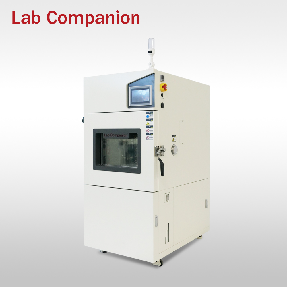
OVEN-256-10W is a high-density test system designed to meet the rigorous performance testing requirements of NVMe SSDs, capable of simultaneously testing up to 256 drives. It operates within a temperature range of -10°C to 85°C and supports the latest PCIe Gen5 x4 interface alongside the NVMe Ver2.0 protocol specification. Each test slot features independent control over SSD power supply voltage, including voltage margining from 0V to 14.5V. Building on a mature framework for SSD production testing, the system offers comprehensive support for R&D pilot testing—including EVT, DVT, and PVT—as well as mass production quality and reliability tests such as MP, ORT, and ODT. Its user-friendly operation and highly flexible configuration significantly enhance both production efficiency and end-product quality in SSD manufacturing.
Product Features
Temperature control range: -10°C to 85°C;
Temperature change rate: 1°C per minute;
Supports PCIe Gen5 x4;
Each test port’s power supply voltage can be controlled via script programming, with an adjustable range of 0.6V – 14.5V and a control accuracy of 1mV;
Compatible with the latest NVMe Ver2.0 protocol and supports user-defined NVMe commands;
Extensive script library and a powerful database analysis system;
LTWolf software supports additional custom features based on client requirements;
Seamless integration with customer MES systems, with optional customization for production data management systems;
Firewall protection design ensures complete isolation between testing circuits and devices under test (DUT);
Comprehensive and proven testing algorithms, including EVT, DVT, RDT, TVM, and more.
Key Considerations for Equipment Handover to Ensure Proper On-Site Operation:
1. Equipment Installation and Commissioning
Our company oversees the transportation and electrical connection of the equipment, ensuring proper operation at the customer's site. All installations strictly comply with the standard acceptance criteria for environmental test chambers. We conduct regular third-party inspections to guarantee continuous adherence to industry standards. Should the customer require an inspection report upon acceptance, we can arrange for an accredited third-party agency to perform on-site testing.
2. Customer Technical Training System
2.1 Basic Operation Training
The training covers equipment startup/shutdown procedures, test program configuration, and routine maintenance protocols. Depending on the user's industry (e.g., third-party testing institutions, automotive manufacturers), the training program is customized to align with specific operational scenarios.
2.2 Advanced Maintenance Training
This program focuses on developing users' troubleshooting and repair capabilities, including humidity system failure diagnosis in temperature-humidity test chambers. Training includes key component replacement procedures and precautions to establish an independent maintenance competency system.
3. Technical Support Service Protocol
3.1 Emergency Response Mechanism
A standardized fault response process ensures technical support is initiated within 2 hours of receiving a service request. Common faults are resolved within 48 hours (with alternative solutions negotiated for remote regions).
3.2 Remote Technical Support
Equipped with a professional remote diagnostic system, real-time video communication or dedicated software access enables rapid fault identification.
4. Spare Parts Supply and Maintenance Assurance
4.1 Spare Parts Management Plan
To enhance after-sales support, we establish dedicated spare parts warehouses for high-volume buyers and repeat clients, enabling rapid response to service needs. Each customer is assigned a dedicated profile to optimize resource allocation.
Priority supply channels are reserved for key partners (e.g., CRCC, CETC), ensuring expedited spare parts delivery to minimize equipment downtime.
4.2 Maintenance Service Policy
Free repairs are provided for non-human-induced failures during the warranty period. Post-warranty maintenance services follow a transparent pricing system, with detailed repair plans and cost estimates provided in advance.
Our company maintains a professional after-sales maintenance team and is committed to continuously improving the technical expertise of our service personnel. We anticipate being able to provide on-site support for international customers in the near future.
A temperature flow meter is a precision instrument used to measure gas flow and temperature, widely applied in environmental monitoring, air conditioning systems, industrial manufacturing, and related fields. Its fundamental principle involves detecting temperature variations caused by gas flow to accurately calculate airflow velocity and volume, thereby providing users with precise data support. The instrument's key features lie in high precision and rapid response. Typically equipped with advanced sensors, it can swiftly capture minute changes in flow rate and provide real-time feedback. Its measurement accuracy remains exceptional even under complex environmental conditions, which is particularly crucial for industrial applications requiring strict control of airflow and temperature. Additionally, the operation of temperature flow meters is relatively simple—users only need basic configuration to obtain required data. This user-friendly design makes it easy for both professionals and general users to operate. Many modern models also feature digital displays with intuitive interfaces, allowing users to quickly understand current status and enhance usability. The instrument demonstrates excellent stability, maintaining consistent measurements over extended periods without significant drift, ensuring data reliability. With continuous technological advancements, many devices now integrate data storage and transmission functions, enabling users to review and analyze historical data post-test for informed decision-making. In conclusion, the thermal anemometer has become an indispensable tool in various industries due to its high precision, rapid response, user-friendly operation, and excellent stability. In daily life and professional settings, mastering this instrument not only enhances work efficiency but also provides crucial support for scientific research and engineering applications. As a vital measurement technology in modern science, it plays a pivotal role in technological advancement.
Selection of the installation site of the rapid temperature change test chamber:
The distance from the adjacent wall can smoothly give full play to the role and characteristics of the environmental test chamber. The long-term temperature of 15 ~ 45 °C and the relative environmental humidity exceeding 86% should be selected. site.
The working temperature of the installation site must not change significantly.
It should be installed on a leveling surface (use a level to determine the level on the road during installation).
It should be installed in a site without sun exposure.
It should be installed in a site with excellent natural ventilation.
It should be installed in areas where flammable materials, explosive products and high-temperature heat sources are eliminated.
It should be installed in a site with less dust.
Install it as close as possible to the switching power supply of the power supply system.
High and low temperature test chamber may encounter a variety of problems in the process of use, the following is a summary of potential faults and their causes from different perspectives:
1. Core system failure
Temperature out of control
Reason: PID control parameters are out of balance, ambient temperature exceeds the design range of the equipment, multi-zone temperature interference.
Case: In a special environment workshop, the external high temperature causes the refrigeration system to overload, resulting in temperature drift.
Humidity is abnormal
Reason: poor water quality of humidification leads to scaling and nozzle blockage, failure of ultrasonic humidifier piezoelectric sheet, and incomplete regeneration of dehumidification desiccant.
Special phenomenon: reverse condensation occurs during high humidity test, resulting in the actual humidity in the box being lower than the set value.
2. Mechanical and structural problems
Air flow is disorganized
Performance: There is a temperature gradient of more than 3℃ in the sample area.
Root cause: the customized sample rack changed the original design air duct and the accumulation of dirt on the centrifugal fan blade led to the destruction of dynamic balance.
sealing failure
New failure: the magnetic force of electromagnetic sealing door decreases at low temperature, and the silicone sealing strip becomes brittle and cracks after-70℃.
3. Electrical and control system
Intelligent control failure
Software level: After firmware upgrade, the temperature dead zone setting error occurs and the historical data overflow causes the program to crash.
Hardware level: SSR solid state relay breakdown causes continuous heating and bus communication is subjected to inverter electromagnetic interference.
Security protection vulnerabilities
Hidden dangers: the synchronous failure of the triple temperature protection relay and the false alarm caused by the expiration of the refrigerant detector calibration.
4. Challenges of special working conditions
Specific temperature shock
Problem: -40℃ to +150℃ rapid conversion of the evaporator weld stress cracking, thermal expansion coefficient difference resulting in the failure of the observation window seal.
Long-term operation attenuation
Performance degradation: after 2000 hours of continuous operation, the compressor valve plate wear leads to a decrease of 15% in refrigeration capacity and drift of ceramic heating tube resistance value.
5. Environmental and maintenance impact
Infrastructure adaptation
Case: The power oscillation of PTC heater caused by the fluctuation of power supply voltage and the water hammer effect of cooling water system damaged the plate heat exchanger.
Preventive maintenance blind spots
Lesson: Ignoring the positive pressure of the box leads to water entering the bearing chamber and biofilm growth and blockage in the condensate discharge pipe.
6. Pain points of emerging technologies
New refrigerant application
Challenges: system oil compatibility problems after R448A replaces R404A, and high pressure sealing problems of subcritical CO₂ refrigeration systems.
IoT integration risks
Fault: The remote control protocol is maliciously attacked, resulting in program tampering and cloud storage failure, resulting in the loss of test evidence chain.
Strategy recommendations
Intelligent diagnosis: configure vibration analyzer to predict the failure of compressor bearing, and use infrared thermal imager to scan the electrical connection points regularly.
Reliability design: key components such as evaporator are made of SUS316L stainless steel to improve corrosion resistance, and redundant temperature control modules are added to the control system.
Maintenance innovation: implement a dynamic maintenance plan based on operating hours, and establish an annual refrigerant purity testing system。
The solutions to these problems need to be analyzed in combination with the specific model of the equipment, the use environment and the maintenance history. It is recommended to establish a collaborative maintenance mechanism including the OEM of the equipment, third-party testing institutions and user technical teams. For key test items, it is recommended to configure a dual-machine hot standby system to ensure the continuity of testing.
(1) Equipment installation and commissioning
On-site service: technical personnel will deliver the goods free of charge and complete the mechanical assembly, electrical wiring and debugging. The debugging parameters shall meet the temperature and humidity, salt spray deposition amount and other indicators in the customer's technical agreement.
Acceptance criteria: provide a third-party measurement report, and unqualified equipment shall be returned or replaced directly. For example, the rain test box shall pass 100% acceptance.
(2) Customer training system
Operation training: covers equipment start and stop, program setting and daily maintenance, customized for different user scenarios such as quality inspection institutions and automobile enterprises.
Deep maintenance training: including fault diagnosis (such as troubleshooting of humidity system in high and low temperature and humidity test chamber) and spare parts replacement to improve customers' independent maintenance ability.
(3) Technical support and response
Instant response: respond to repair demand within 15 minutes, and solve routine faults within 48 hours (negotiate with remote areas).
Remote diagnosis: through video guidance or remote access software, quickly locate the problem (such as abnormal dust concentration in the sand test chamber).
(4) Spare parts supply and maintenance
Make spare parts plan, give priority to the supply of wear and tear parts from cooperative units (such as China Railway Inspection and Certification Center, China Electronics Technology Group), and reduce downtime.
Non-manual damage is free of charge during the warranty period, and paid services are provided after the warranty period with transparent charges.
(1) Equipment Installation & Debugging
On-Site Services: Free delivery, assembly, wiring, and debugging by technicians. Parameters (temperature, humidity, salt spray settlement, etc.) must meet the client’s technical agreement.
Acceptance: Third-party calibration reports provided. Non-compliant equipment (e.g., rain test chambers requiring 100% pass rate) will be replaced immediately.
(2) Customer Training
Basic Training: Startup/shutdown, programming, and maintenance, customized for users (e.g., QA agencies, automakers).
Advanced Training: Fault diagnosis (e.g., humidity system issues in thermal chambers) and part replacement to enhance self-repair capability.
(3) Technical Support
Rapid Response: 15-minute reply to requests, 48-hour resolution for common issues (remote areas negotiated).
Remote Aid: Video guidance or software access for quick troubleshooting (e.g., abnormal dust concentration in sand/dust test chambers).
(4) Spare Parts & Maintenance
Priority Supply: Critical parts prioritized for partners (e.g., CRCC, CETC) to minimize downtime.
Transparent Costs: Free repairs for non-human damage during warranty; post-warranty services at clear rates.
1. Communicate with manufacturers directly to customize requirements
operating steps :
Requirement submission: clear the test object (such as headlights, batteries, sensors, etc.), test scenario (such as simulated extreme cold wading, high temperature and high pressure spraying) and industry specifications (such as automobile, military, electronics);
Technology docking: provide product parameters (size, weight), environmental conditions (temperature range, impact frequency) and special requirements (such as salt spray superposition test, dynamic Angle adjustment);
Confirmation of the scheme: Based on general standards such as GB, IEC and GJB, and industry specifications such as VW 80101 and ISO 16750, the manufacturer designs customized test procedures and equipment configuration schemes.
2. Adapt to the existing standard framework
Manufacturers can expand or adjust based on the following criteria:
national standards :
GB/T 28046.4-2011: For the climate load test of automotive electrical equipment, the core parameters such as temperature, time and circulation times of ice water impact are defined;
GB/T 2423.1: Environmental test specification for general electrical and electronic products, supporting the design of calibration and verification process.
codes of practice :
VW 80101-2005: Volkswagen Electric Components Test Standard, applicable to the refinement of parameters such as spray pressure and water temperature accuracy;
GMW3172: General Motors global engineering standard, supporting multi-environment composite testing (such as ice water impact + salt spray corrosion);
ISO 16750-4:2006: International common vehicle electrical equipment test framework, compatible with customized cycles (e.g. 100 standard or 200 enhanced).
Third, optimize standards by using manufacturers' technical resources
Flexible parameter adjustment:
Temperature range: standard high temperature range 65~160℃, can be extended to-70℃ to +150℃;
Water splashing system: support flow (3~4L/3S or 80L/min), distance (325±25mm adjustable), nozzle type (gap/matrix) and other customization;
Intelligent control: the PLC system can customize the temperature switching rate (such as 20 seconds to complete the conversion from extreme cold to high temperature), data acquisition frequency and report format.
Function module superposition:
Compatible with multiple test requirements such as waterproof (IPX5-6) and dustproof (IP5X-6X);
Support dynamic Angle spraying (15 ~75 adjustable), salt spray composite test and other complex scene simulation.
4. Ensure compliance through certification and verification
Equipment calibration: the manufacturer provides half-year temperature sensor calibration service, the error is controlled within ±2℃;
Third-party verification: it is recommended to certify the temperature change rate, uniformity and other indicators of customized equipment through quality inspection institutions (such as China Electric Power Research Institute, FAW test site);
Data traceability: The test chamber supports USB export of test logs, which is convenient for quality traceability and standard iteration.
5. Service support and case reference
Technical team: Guangdong Hongzhan cooperates with universities and research institutes to provide whole-process support from demand analysis to standard implementation;
Case library invocation: You can refer to the car company case (such as 800V battery pack IPX9K test, intelligent lamp cold and hot cycle verification) to optimize and customize the standard;
After-sales guarantee: customized equipment enjoys 1 year warranty and 48 hours door-to-door maintenance to ensure the stability of standard implementation.
The Guangdong Hongzhan Dust Test Chamber is primarily used to simulate natural sand and dust environments, testing the dust resistance of various products. In industries such as electronics, automotive, and aerospace, products may face challenges from sand and dust. If a product's dust resistance is inadequate, sand and dust particles can penetrate the equipment, leading to malfunctions, performance degradation, or even damage. Therefore, accurately assessing a product's dust resistance is crucial, and the Guangdong Hongzhan Dust Test Chamber provides a reliable testing platform for companies.
(1) Box structure: combination of robust and durable and sealing
The test chamber is constructed from high-quality stainless steel, which not only provides excellent corrosion resistance and protection against sand and dust erosion but also ensures good sealing to prevent sand and dust leakage, maintaining the stability of the testing environment. The interior is meticulously divided into functional areas such as the sample testing zone, sand and dust circulation duct, heating system, and control system, facilitating both operation and maintenance.
(2) Dust generation system: accurate simulation of dust environment
This is one of the core components of the test chamber. It consists of a sand and dust storage unit, a sand and dust conveying unit, and a sand and dust dispersion unit. The storage unit can hold sand and dust of various sizes and compositions as required by the test. The conveying unit delivers the sand and dust into the test chamber using either a screw conveyor or an air conveying method. The dispersion unit ensures that the conveyed sand and dust is evenly distributed in the air, creating a stable and suitable sand and dust environment for testing, ensuring that each sample is thoroughly tested under uniform conditions.
(3) Air circulation system: create stable dust airflow
The air circulation system consists of a fan, ducts, and an air filter. The fan provides the necessary power to ensure the air circulates within the test chamber. The ducts guide the airflow effectively, ensuring that the air passes through the sand and dust generation system and the sample testing area, allowing the sand and dust to fully contact the samples. The air filter effectively removes sand and dust particles from the circulating air, protecting the fan and other equipment from damage and extending their lifespan.
(4) Control system: intelligent and accurate operation core
The control system employs an advanced programmable logic controller (PLC) and a touch screen interface. Operators can easily set and monitor test parameters, such as temperature, humidity, dust concentration, and wind speed, via the touch screen. It also features automatic adjustment capabilities, allowing it to continuously monitor and precisely adjust the various parameters inside the test chamber according to preset values, ensuring that the testing environment always meets the required standards. Additionally, the control system includes fault alarm and protection functions, which can promptly issue warning signals and take protective measures in case of any abnormal conditions, ensuring the safety of both equipment and personnel.
(5) Complete workflow: efficient and rigorous testing process
During the preparation phase, operators select appropriate sand and dust particles based on the test requirements and place them in the storage device. They then clean and inspect the test chamber and properly position the samples within the testing area. Once the test chamber is activated, the sand and dust generation system begins to operate, conveying and dispersing the sand and dust into the air. The air circulation system ensures a stable flow of sand and dust air. The control system continuously monitors and adjusts various parameters to maintain a stable test environment. During the sample testing phase, the test chamber operates according to the set schedule
When the Guangdong Hongzhan ice water impact test chamber is used in summer, the following matters should be paid special attention to to ensure the stable operation of the equipment and the accuracy of the test results:
1. Environment and heat dissipation management
Enhance ventilation and heat dissipation High temperature in summer is easy to lead to the decrease of equipment heat dissipation efficiency. Ensure that at least 10cm space is reserved around the equipment to promote air circulation. If the equipment adopts air cooling system, the condenser surface dust should be cleaned regularly to prevent poor heat dissipation and overheating of the compressor.Control the environmental temperature and humidity. Avoid placing the equipment in the direct sunlight area. It is recommended that the laboratory temperature be kept at 25±5℃ and the humidity be lower than 85%. High temperature and high humidity environment may accelerate the accumulation of frost or condensation water on the equipment, so it is necessary to increase the dehumidification measures.
2. Refrigeration system maintenance
Water quality and tank management Bacteria are easy to breed in summer, so use deionized water or pure water to avoid hard water scaling and blocking pipes. It is recommended to change the tank water every 3 days, and empty and clean the tank before long-term disuse.Refrigeration efficiency monitoring High temperature environment may lead to overload operation of the refrigeration system. The compressor oil condition should be checked regularly to ensure sufficient refrigerant. If the water temperature exceeds the set value (such as 0~4℃), the machine should be stopped immediately for troubleshooting.
3. Frosting and defrosting treatment
Prevent frost aggravation When the humidity is high in summer, the frost rate inside the equipment may accelerate. It is recommended to perform a manual defrosting process after 10 cycles: set the temperature to 30℃ and keep it for 30 minutes, and then drain water to clean the ice crystals on the evaporator surface.
Optimize the test interval to avoid continuous long-term low temperature testing. It is recommended to reserve 15 minutes of buffer time between high temperature (e.g., 160℃) and ice water shock cycle to reduce the impact of thermal stress on the equipment.
4. Adjustment of operation specifications
Parameter setting optimization According to the characteristics of the summer environment, the normal temperature recovery stage time can be shortened appropriately (the reference standard is to complete the temperature switch within 20 seconds), but it must ensure that it meets the requirements of GB/T 2423.1 or ISO16750-4 standards.Safety protection should be strengthened. Anti-freezing gloves and goggles should be worn during operation to avoid the adhesion of hands and low-temperature parts caused by sweating. Before opening the door after high temperature test, the temperature inside the box should be confirmed to be below 50℃ to prevent scalding from hot steam.
5. Emergency and long-term shutdown preparation
Fault response If the equipment has E01 (temperature out of tolerance) or E02 (water level abnormal) alarm, you should immediately cut off the power supply and contact the technical support of the manufacturer. Do not disassemble the refrigeration pipeline by yourself.Long-term protection When not used for more than 7 days, the water tank should be emptied, power should be cut off and dust cover should be covered. At the same time, power should be on for 1 hour every half a month to keep the circuit board dry.
Through the above measures, the impact of high temperature and humidity environment in summer on the ice water shock test chamber can be effectively reduced to ensure the reliability of test data and the service life of the equipment. The specific operation details should be adjusted according to the equipment manual and actual working conditions.
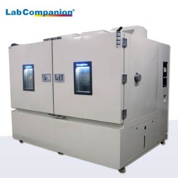
The high and low-temperature impact test chamber is designed for reliability testing of industrial products under both high and low temperatures. It is used to evaluate the performance of components and materials in industries such as electronics, automotive, aerospace, shipbuilding, and weaponry, as well as in higher education and research institutions, under alternating cycles of high and low temperatures. The main features include:
Excellent Conductivity: The alloy cable, made by adding rare earth elements and copper, iron, silicon, and other elements from China, undergoes special processing to achieve a conductivity 62% higher than that of copper. After this process, the cross-sectional area of the alloy conductor is increased by 1.28 to 1.5 times, making the cable's current-carrying capacity and voltage drop comparable to those of copper cables, effectively replacing copper with new alloy materials.
Superior Mechanical Properties: Compared to copper cables, the rebound performance of the high and low-temperature impact test chamber is 40% lower, and its flexibility is 25% higher. It also has excellent bending properties, allowing for a much smaller installation radius compared to copper cables, making it easier to install and connect terminals. The special formulation and heat treatment process significantly reduce the creep of the conductor under heat and pressure, ensuring that the electrical connections of the alloy cable are as stable as those of copper cables.
Reliable Safety Performance: The high and low-temperature impact test chamber has been rigorously certified by UL in the United States and has been in use for 40 years in countries like the United States, Canada, and Mexico without any issues. Based on advanced American technology, the test chamber has been tested and inspected by multiple domestic institutions, ensuring its reliable safety.
Economic Performance Savings: When achieving the same electrical performance, the direct procurement cost of high and low-temperature impact test chambers is 20% to 30% lower than that of copper cables. Since alloy cables are only half the weight of copper cables and have excellent mechanical properties, using alloy cables can reduce transportation and installation costs by more than 20% in general buildings and over 40% in large-span buildings. Using high and low-temperature impact test chambers will have an immeasurable impact on building a resource-efficient society.
Excellent Anti-corrosion Performance: When exposed to air at high temperatures, alloy cables immediately form a dense oxide layer that is highly resistant to various forms of corrosion, making them suitable for harsh environments. Additionally, the optimized internal structure of the alloy conductor and the use of silane cross-linked polyethylene insulation material extend the service life of alloy cables by more than 10 years compared to copper cables.
1. Dust adhering to the condenser can cause the high-pressure switch of the compressor to trip and issue false alarms. Therefore, dust attached to the cooling grid of the condenser can be removed with a vacuum cleaner every month, or by using a hard-bristled brush after turning on the machine, or by blowing it off with a high-pressure air nozzle.2. The area around the machine and the ground at the bottom should be kept clean at all times to prevent a large amount of dust from being sucked into the unit or reducing equipment performance and causing accidents.3. When opening or closing the door or taking samples from the test chamber, do not touch the sealing strip on the door.4. The core of the constant temperature and humidity test chamber - the refrigeration system should be inspected once a year. Check for leaks in the copper tubes and at each joint and interface. If there are any, inform the manufacturer.5. The humidifier and water tank should be cleaned frequently to avoid scaling and affecting steam emission. Clean them after each test. Timely descaling helps extend the lifespan of the humidification tube and ensures smooth water flow. When cleaning, use a copper brush and then rinse with water.6. The distribution room should be cleaned and inspected more than once a year. Loose nodes can put the entire equipment in a dangerous working state, burn out components, cause fires, alarms, and endanger lives.7. The dry and wet bulb wicks should be checked frequently. Replace them promptly if they become hard or dirty. It is recommended to replace them every three months.8. Inspection and maintenance of the water circuit. The water pipes in the water circuit are prone to clogging and leakage. Regularly check for leaks or blockages. If found, remove them promptly or notify the manufacturer.


 Get A Quote


 IPv6 network supported