LED Traffic Light Test
Light-emitting Diode, referred to as LED, is the abbreviation of the English name Light Emitting Diode, through the combination of electrons and holes to release energy light, can efficiently convert electrical energy into light energy, has a wide range of uses in modern society, such as lighting, flat panel display and medical devices. With the continuous progress of technology, this electronic component from the early can only emit low-light red light to develop other monochromatic light, has been widely used in visible light, infrared and ultraviolet light, is widely used in indicators and display boards, and then extended to traffic lights. It is known as a new light source in the 21st century, with high efficiency, long life, material is not easily affected by the environment and relatively stable, with the advantages of traditional light sources can not be comparable.
The traffic on the zebra crossing is heavy every day, as the guide of the traffic rules - the traffic light is also working hard every day, because it is placed outdoors all year round, so it must accept the strict reliability test before it can work. The test conditions include: Voltage electric, failure protection, electromagnetic noise, dust and waterproof, high temperature test, vibration test, salt spray test, insulation voltage, insulation resistance test...
Note: Before other tests, LED traffic lights need to undergo dry heat tests before other tests can be carried out.
Lamp surface test: dry heat test: 60℃/24 hours/applied voltage
Failure judgment: no deformation, loosening, falling off
Temperature resistance test: 70℃(16 hours)→-15℃(16 hours)→R.T., RAMP:≦1℃/min, 2cycle, power supply
Temperature and humidity test: 40℃→RAMP:≦1℃/min→40℃/95%(24 hours), power on
Continuous switching action: 40℃/60~80%, ON(1sec)←→OFF(1sec), 10000 times
Voltage electric: 80 ~ 135V(AC), 170 ~ 270V(AC)
Failure judgment: Light intensity drift ≦20%(110V, 220V light intensity as the benchmark)
Waterproof and dustproof meet IP54 class requirements
Insulation resistance test:
Insulation resistance: 500V
Failure determination: not less than 2MΩ
Insulation withstand voltage test: 1000V/60Hz/1min(after insulation resistance test)
Light chamber test:
High temperature test: 130℃/1 hour
Failure judgment: no deformation, loosening, falling off, cracking... Etc.
Vibration test: XYZ three-way, each 12min for 36min, 10 ~ 35 ~ 10Hz sine wave, each cycle for 3min, total vibration of 2mm
Failure judgment: no deformation, loosening, falling off, cracking, and the LED light surface can be normally lit and operated
Wind tunnel test: Wind speed 16 (51.5-56.4m /s), forward (0 degrees) and side (45 degrees), each blowing for 2 hours
Failure judgment: no deformation, loosening, falling off, cracking
Salt spray test: 96 hours
Failure determination: less than 8 embroider points on the area of 10,000mm^2, LED signal light surface insulation resistance >2MΩ, voltage 1000V/1min, no abnormality
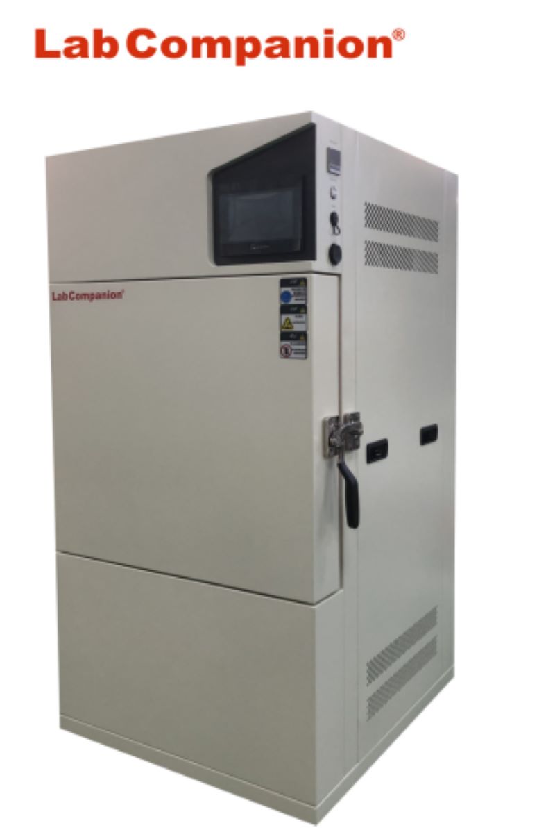
Recommended model 1: high temperature and high humidity test chamber
High temperature and high humidity test chamber is suitable for electrical, electronic, instruments and other products, parts and materials in high and low temperature alternating wet and hot environment storage, transportation, use adaptability test; It is a reliability test equipment for all kinds of electronic, electrical, electrical, plastic and other raw materials and devices to carry out cold resistance, heat resistance, wet resistance, dry resistance test and quality control engineering; Especially suitable for fiber, LCD, crystal, inductance, PCB, battery, computer, mobile phone and other products of high temperature resistance, low temperature resistance, moisture resistance cycle test.
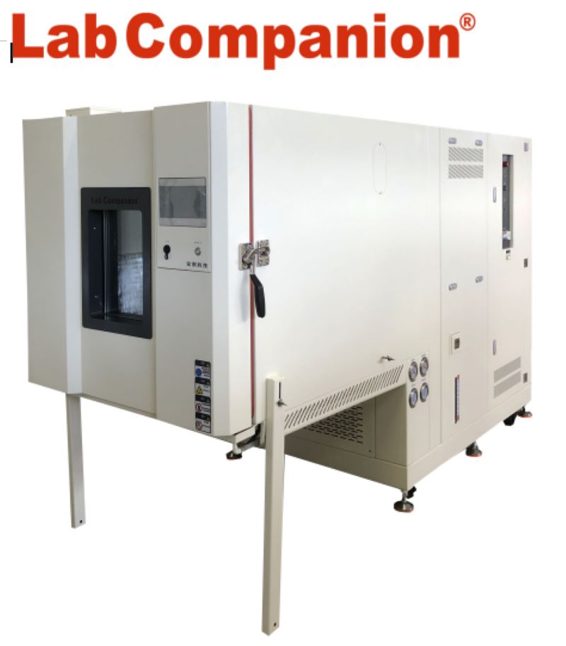
Recommended model 2: vibration of the comprehensive chamber
Vibration of the comprehensive chamber combined with temperature, humidity, vibration function in one, suitable for aerospace products, information electronic instruments, materials, electrical, electronic products, all kinds of electronic components in a comprehensive harsh environment to test their performance indicators. Vibration of the comprehensive chamber mainly for aerospace, aviation, petroleum, chemical, electronics, communications and other scientific research and production units to provide temperature and humidity change environment, at the same time in the test chamber will be electric vibration stress according to the specified period of the test on the test, for the user of the whole machine (or components), electrical appliances, instruments, materials for temperature and humidity, vibration comprehensive stress screening test. In order to assess the adaptability of the test product or to evaluate the behavior of the test product. Compared with the effect of a single factor, it can more truly reflect the adaptability of electrical and electronic products to temperature, humidity and vibration complex environment changes in transportation and actual use, and expose product defects, which is an essential and important test means for the whole process of new product development, prototype test and product qualification test.
Recommended model 3: salt spray test chamber
The salt spray test chamber is suitable for all kinds of communication electronic products, electronic appliances, hardware parts to do neutral salt spray test (NSS) and corrosion test (AASS, CASS), omplied with CNS, ASTM, JIS, ISO and other standards. The salt spray test is to test the corrosion resistance of the products on the surface of various materials after anti-corrosion treatment such as coating, electroplating, anodic treatment and anti-rust oil.
Recommended model 4: waterproof and dustproof test chamber
Waterproof and dustproof test chamber is suitable for outdoor terminals such as metering automation terminals and distribution network automation terminals to carry out rain and dust tests to ensure that the tested products can withstand the impact of harsh environmental changes, so that the products can operate safely and reliably, and are suitable for external lighting and signal devices and automotive lamp shell protection. It can provide realistic simulation of various environments such as water, spray and dust tests that electronic products and their components may be subjected to during transportation and use. In order to detect the waterproof and dustproof performance of various products.
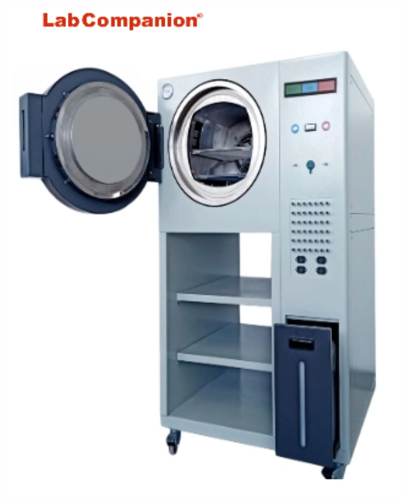
Product Characteristics of Vacuum Oven
The vacuum oven can obtain a higher drying rate at a lower temperature, and the heat utilization is full, which is mainly suitable for the drying of heat-sensitive materials and materials containing capacitors and solvents to be recovered. It can be treated before drying, and no debris can be mixed in the drying process. The dryer is a static vacuum dryer, so the formation of dry materials will not be damaged. There are many eating methods: steam, hot water, thermal oil and electric heating.
Vacuum ovens are designed for drying heat-sensitive, easily decomposed and easily oxidized substances, and can be filled with inert gases, especially for some complex items.
The product has the following features:
1, chamber structure: chamber adopts integral structure;
2, shell material: high-quality cold-rolled steel electrostatic spray; Inner wall material: stainless steel plate;
3, insulation material: ultrafine glass fiber;
4, the door seal: environmental protection silicone rubber strip. The closure and tightness of the box can be adjusted, and the silicone rubber door sealing ring is formed as a whole to ensure a high vacuum inside the box.
5, the studio is made of stainless steel plate (or wire drawing plate) to ensure that the product is durable.
6, storage, heating, testing and drying are carried out in an environment without oxygen or full of inert gases, so there is no oxidation.
7, the shortest heating time, compared with the traditional drying oven heating time reduced by more than 50%. Because the vacuum oven is provided with heat energy by electricity, and the wet items are conductive, it is advisable to be careful not to have leakage in use, so the general oven should be grounded to ensure safety. If there is no ground wire, it is necessary to confirm that there is no leakage of electricity in the oven; If there is no leakage, it can be used with care, and if there is still leakage, it should be stopped immediately.
Vacuum oven is designed for drying heat-sensitive, easily decomposed and easily oxidized substances, can be filled with inert gas (optional), especially some complex components of the articles can also be fast drying, suitable for industrial and mining enterprises, medical schools, scientific research units in vacuum conditions for drying heat treatment.
Smart Watch Reliability Test Conditions
In today's society, elementary school students and even kindergarten children have a smart watch. So, what is a smartwatch? In the late period of sports watch promotion due to the rapid takeoff of smart phones, the smart table has no intention to provide the same PIM effect as PDA and smart phones, and appeals to the smart phone agent assistant accessories, similar to Bluetooth headphones are voice AIDS of smart phones, smart tables become information and data AIDS, providing more convenient and fast information display and operation. There are also other names such as Smart Accessory and Android Remote. Positioned as a mobile phone assistant, the idea is that "the reason why the pocket watch is extinct is because it is simply to look at the time, but also take out the pocket, about 2-3 seconds, but the watch is less than 1 second, which is more convenient than the pocket watch." And after observation, now everyone takes out a smartphone and slides open, just to confirm the message, so that about dozens of times, these confirmation even typing reply do not need, if the dozens of confirmation changed on the watch, you do not always have to pull the machine slide unlock, because this is as time-consuming as a pocket watch. Therefore, after becoming the assistant of the mobile phone, the remote control, if you do not take the mobile phone to go out, the watch is useless in addition to showing the time, and the Bluetooth headset without a mobile phone, almost scrap metal.
Combined with smart bracelet to sell better!!
Smart watch from "smaller than the PDA independent computer" to "smart phone remote control AIDS", seems to have been a more successful positioning, but this CES 2014 can be seen, combined with smart bracelet positioning is better. The smart wristband uses acceleration sensors (and gyroscopes, magnetoresistive sensors, etc.) to sense the user's running speed, step count, etc., and can even detect deep sleep and provide suggestions for exercise and sleep. When the wristband is added to the display, it can display the time and information on the mobile phone. Appeal to mobile phone information, if there is no urgent information needs, in fact, only similar to the Bluetooth headset is regarded as an option (Courier, driver need), if everyone can accept the information access speed of sliding, then the market will be limited. However, in addition to the appeal for exercise and sleep record supervision, and emphasize information tips, rather than emphasizing the remote control of the watch on the mobile phone, it is equivalent to a little sacrifice or almost no sacrifice to the end user, but it brings immediate and new application value (sports, sleep assistance), rather than completely repeating the efficacy value of the mobile phone, which further increases the market success of the smart watch. After constantly adjusting the efficacy, application and positioning, and integrating with the smart ring, we believe that we can have a higher market than in the past.
Smart watch for people and functions:
1. Smart watches for adults
Functions: Bluetooth synchronous mobile phone calls, send and receive text messages, monitor sleep, monitor heart rate, sedentary reminder, running, remote photography, music playback, video, compass and other functions, designed for fashion trend people!
2, Smart watch for the elderly
Functions: ultra-accurate GPS positioning, family calls, emergency calls, heart rate monitoring, sedentary reminders, medicine reminders and other customized functions for the elderly, providing an umbrella for the elderly's travel, bring this watch, refuse to lose the elderly!
3, Children positioning smart watch
Functions: multiple positioning, two-way call, SOS SOS, remote monitoring, intelligent anti-loss, historical track, electronic fence, pedometer, love reward and other functions, to ensure the safety of children, give children a healthy and safe growth environment!
Smart watch specification:
IEC 60086-3: Watch batteries
ISO 105-A02: Colour fastness test -A02 - Grey scale assessment for discoloration
ISO 105-A03-1993: Tests for colour fastness -A03- Grey scale assessment of dyeing
ISO 764: Horological anti-magnetic watches
ISO 1413: Horological shockproof watches
ISO 2281: Horological waterproof watches
ISO 11641-1993: Leather - tests for colour fastness - Colour fastness to perspiration
ISO 14368-3: Impact resistance test of table glass
MIL 810G: Environmental engineering considerations and laboratory testing
QB/T 1897-1993: Waterproof watch inspection
QB/T 1898-1993: Inspection of shockproof watches
QB/T 1908-1993: Key reliability test
QB/T 1919-2012: Type inspection of digital quartz watches with hands and liquid crystal
QB/T 2047-2007: Inspection of metal watchbands
GB/T 2537-2001: leather color fastness test reciprocating grinding color fastness
QB/T 2540-2002: Leather strap inspection
GB/T 6048-1985: digital quartz electronic watch
GB/T 18761-2007: electronic digital display indicator
GB/T 18828-2002: Standard for diving watches
GB/T 22778-2008: LCD digital quartz stopwatch type inspection
GB/T 22780-2008: Type inspection of LCD quartz watches
GB/T 26716-2011 idt ISO 764-2002: Inspection of anti-magnetic watches
HJ216-2005: Eco-Drive watch
Smart watch pilot project:
Reliability, time period measurement accuracy, instantaneous daily difference, operating temperature, voltage range, average temperature coefficient, voltage coefficient, moisture resistance, shock resistance, waterproof performance, battery replacement cycle, key fatigue resistance, light and weather resistance, antistatic performance Ambient temperature range: -25℃ ~ 55℃ Operating temperature: -5 ~ 50℃/80%R.H.(Requirements: each function and liquid crystal display should be complete and normal) High and low working temperature test: 50±1℃/24h→RT/1h→-5±1℃ Temperature change test conditions: (IEC60068-2) High temperature: 30, 40, 55℃ Low temperature: 5, -5, -10, -25℃ Nb residence time (including rising and cooling time) : 10min, 30min, 1hr Nb temperature variability: 3±0.6℃/min, 5±1℃/min.
Wet heat test:
1.40±1℃/85 ~ 95%R.H./24h
2.8±1℃/85 ~ 95%R.H./4h
Warehouse storage humidity test:
40℃/20%, 30%, 40%, 50%, 60%, 70%, 80%, 90%
49℃/10%, 20%, 30%, 40%, 50%, 60%, 70%, 80%, 90%
Each step37 hours
Air transport temperature change simulation test:
Specification: IEC60721.2 Electrical and electronic products application environmental conditions - transport national standard
Category: 2K5 (Applicable to the climatic range of unventilated and unpressurized internal transport worldwide)
Temperature range: -65℃←→85℃
RAMP: 5℃/min
Air transport temperature change simulation test:
Specification: IEC60721.6 Electrical and electronic products application environmental conditions - Marine
Category: 6K5 (subject to cold weather, installed in weather-protected but unheated parts)
Temperature range: -25℃←→40℃
RAMP: 3℃/min
Water temperature change resistance test:
5min in 40℃ water → 5min in 20℃ water, 5min in 40℃ water, water depth of 10cm
Water pressure resistance test:
Soak the watch in a container of water, apply an overpressure of 2*10^5Pa[or 20m water depth] within 1 minute, maintain 10 minutes, and then in 1 minute the pressure will be to the standard pressure of the surrounding environment
Salt water resistance test:
Put the watch under test into 30g/L sodium chloride solution at 18 ° C ~ 25 ° C for 24h. Check the case and accessories after the test should not have significant changes; Check the moving parts, especially the rotating front ring should be able to maintain normal function
Underwater reliability test:
The watch under test is immersed in 30cm±2cm of water and placed at a temperature of 18 ° C ~ 25 ° C for 50h, and all mechanical devices should still work normally. During the test, mechanical devices that need to be operated in water, such as time presetting devices and light switches, should be able to work normally; Do condensation test, the inner surface of the table glass shall not appear condensation fog, and the mechanical function should not be damaged
Thermal shock resistance test:
Immerse the watch in water of different temperatures with a depth of 30cm±2cm successively: place it in water of 40 ° C ±2 ° C for 10 minutes; Put in 5℃±2℃ water for 10 minutes; Put in water at 40 ° C ± 2 ° C for 10 minutes (the watch shall not be removed from the water and re-immersed in another water temperature for more than 1 minute). Do condensation test, the inner surface of the table glass shall not appear condensation fog, and should operate normally.
Chemical resistance test:
Citation Specifications: ASTM F 1598-95, ASTM D 1308-87, ASTM D 1308-02
Ingredients: Household chemicals (dirt, dust, oil, fumes and peanut butter, cosmetics, hand cream... Etc.)
Time: 24 hours
Corrosion resistance to artificial sweat test:
QB/T 1901.2-2006 "Gold alloy covers of shell and its accessories - Part 2 Test for purity, thickness, corrosion resistance and adhesion"
Test principle: The artificial sweat is used to contact the object under high temperature (40±2) ℃, and after a long time (not less than 24 hours), the condition of its surface is observed to determine its resistance to sweat corrosion.
Vibration test:
Acceleration (19.6m/s^2), frequency 30Hz ~ 120Hz, scanning cycle 1min
Requirements: The functions and the LCD display should be complete and normal, and the parts should not be loose and fall off
Drop test:
1m drop lithographic hardwood, once watch side, once surface glass
Requirements: Normal function after each impact, no appearance damage [broken glass, case foot bent, case component bent, case broken, button damaged]
Impact test:
Impact cone pad material: polytetrafluoroethylene, impact speed 4.43m/s, impact height 1m
Arm swing test:
2 to 10Hz
Drug Stability Test
The effectiveness and safety of drugs have attracted much attention, and it is also a livelihood issue that the country and the government attach great importance to. The stability of drugs will affect the efficacy and safety. In order to ensure the quality of drugs and storage containers, stability tests should be performed to determine their effective time and storage state. Stability test mainly studies whether the quality of drugs is affected by environmental factors such as temperature, humidity and light, and whether it changes with time and the correlation between them, and studies the degradation curve of drugs, according to which the effective period is presumed to ensure the effectiveness and safety of drugs when used. This article collects the standard information and test methods required for various stability tests for customers' reference.
First, drug stability test criteria
Storage conditions of drugs:
Storage conditions (Note 2)
Long-term experiment
25℃±2℃ / 60%±5%RH or
30℃±2℃ /65%±5% RH
Accelerated test
40℃±2℃ / 75%±5%RH
Middle test (Note 1)
30℃±2℃ / 65%±5%RH
Note 1: If the long-term test condition has been set at 30℃±2℃/65% ±5%RH, there is no middle test; if the long-term storage condition is 25℃±2℃/ 60% ±5%RH, and there is a significant change in the accelerated test, then middle test should be added. And should be assessed against the criteria of "significant change".
Note 2: Sealed impervious containers such as glass ampoules can be exempted from humidity conditions. Unless otherwise determined, all tests shall be carried out in accordance with the stability test plan in the interim test.
The accelerated test data should be available for six months. The minimum duration of the stability test is 12 months for the middle test and the long-term test.
Store in refrigerator:
Storage conditions
Long-term experiment
5℃±3℃
Accelerated test
25℃±2℃ / 60%±5%RH
Stored in freezer:
Storage conditions
Long-term experiment
-20℃±5℃
Accelerated test
5℃±3℃
If the product containing water or solvents that may be subject to solvent loss is packaged in a semi-permeable container, the stability assessment should be conducted under low relative humidity for a long period of time, or an middle test of 12 months, and an accelerated test of 6 months, in order to prove that the drug placed in the semi-permeable container can withstand the low relative humidity environment.
Containing water or solvents
Storage conditions
Long-term experiment
25℃±2℃ / 40%±5%RH or 30℃±2℃ /35%±5% RH
Accelerated test
40℃±2℃;≤25%RH
Middle test (Note 1)
30℃±2℃ / 35%RH±5%RH
Note 1: If the long-term test condition is 30℃±2℃ / 35%±5%RH, there is no middle test.
The calculation of the relative water loss rate at a constant temperature of 40℃ is as follows:
Substituted relative humidity (A)
Control relative humidity (R)
Water loss rate ratio ([1-R]/[1-A])
60%RH
25%RH
1.9
60%RH
40%RH
1.5
65%RH
35%RH
1.9
75%RH
25%RH
3.0
Illustration: For aqueous drugs placed in semi-permeable containers, the water loss rate at 25%RH is three times that of 75%RH.
Second, Drug stability solutions
Common drug stability test criteria
(Source: Food and Drug Administration, Ministry of Health and Welfare)
Item
Storage conditions
Long-term experiment
25°C /60% RH
Accelerated test
40°C /75%RH
Middle test
30°C/65%RH
(1) Wide temperature range test
Item
Storage conditions
Long-term experiment
Low or sub-zero temperature conditions
Accelerated test
Room temperature and humidity or low temperature conditions
(2) Test equipment
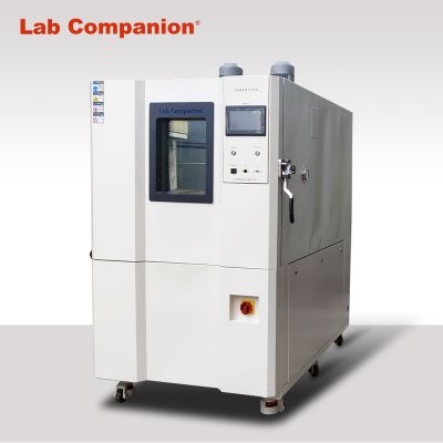
1. Constant temperature and humidity test chamber
2. Drug stability test chamber
Solar Module Test
Solar energy is a kind of renewable energy, refers to the sun's thermal radiation energy, the main performance is often said that the sun rays, in the modern generally used for power generation or to provide energy for water heaters. In the case of decreasing fossil fuels, solar energy has become an important part of human energy use and continues to develop. The use of solar energy has two ways of photothermal conversion, solar power generation is an emerging renewable energy, so the related solar energy research and application industry has also stepped up the pace of development. In the research and production process of the solar module, the relevant reliability test and environmental test specifications have been formulated to ensure that the solar module can be durable for more than 20 to 30 years and its power generation conversion rate when used in outdoor environment.
Solar module HAST and PCT test illustration
Temperature and humidity test IEC61215-10-13:
Temperature and humidity test conditions are 85℃/85%R.H., time: 1000 hours, to determine the ability of the module to resist long-term moisture penetration, through the temperature and humidity test can be found defects: CELL delamination, EVA(delamination, discoloration, bubble generation, atomization, Browning), string line blackening, TCO corrosion, solder joint corrosion, Thin-film yellow discoloration, junction box degumming off... However, according to the test results of relevant Solar plants,1000 hours is not enough, and the actual situation finds that the test time to enable the module to find the problem needs to be at least 3000 to 5000 hours.
Test method of HAST [Highly Accelerated Temperature and Humidity Stress Test]:
HAST is short for Highly Accelerated Temperature and Humidity Stress Test in English. The highly accelerated humidity resistance evaluation test method is based on the environmental parameters of temperature and humidity. HAST and PCT [Pressure Cooker Test] are different from the two tests, HAST is called unsaturated test, while PCT is saturated humidity test, and the biggest difference from the general humidity evaluation test method is that it is in the field of temperature and humidity above 100℃, and is in the high-density water vapor environment test. The purpose of HAST is to accelerate the test of humidity intrusion into the sample for humidity resistance evaluation by taking advantage of the fact that the water vapor pressure in the test tank is much higher than the water vapor partial pressure inside the sample.
Test specifications and conditions of JESD22-A118[Accelerated Moisture Resistance-Unbiased](HAST unbiased test) :
It is used to evaluate the reliability of the device in wet environment, that is, the penetration of harsh temperature, humidity and increased water vapor pressure through the external protective material (encapsulation or sealing material) or along the interface of the external protective material and metal conductor, the failure mechanism is the same as that of the [85℃/85%RH] high temperature and high humidity steady-state humidity life test (JESD22-A101-B). In this test process, no bias is applied to ensure that the failure mechanism is not covered by bias, and this test is used to determine the failure mechanism in the package. The sample is in a non-condense humidity environment, only the temperature is increased a little, and the failure mechanism is the same as the [85℃/85%RH] high temperature and high humidity steady-state humidity life test without bias. It should be noted that, Since absorbed water vapor reduces the glass transition temperature of most polymer materials, an unreal failure mode may occur when the temperature is higher than the glass transition temperature.
85℃/85%/1000H(JESD22-A101)→110 ℃/85%/264H(JESD22-A110, A118)
Specifications: JEDEC22-A110(with bias), JEDEC22-A118(without bias)
Common conditions: 110℃/85%R.H./264h Applicable: PET, EVA, modules
Test method of PCT [Pressure Cooker Test]:
Generally known as the pressure cooker cooking test or saturated steam test, the most important is to test the product under harsh temperature, saturated humidity (100%R.H.)[saturated water vapor] and pressure environment, test the high humidity resistance of the test product, for solar packaging materials or modules, used for material moisture absorption test, high pressure cooking... For the purpose of the test, if the product to be tested is a Cell, it is used to test the moisture resistance of the Cell. The product to be tested is placed in a harsh temperature, humidity and pressure environment for testing. If the package is not well packaged, moisture will penetrate into the package along the colloid or the interface between the colloid and the wire frame. Popcorn effect, open circuit caused by metal wire corrosion, short circuit caused by contamination between package pins... And other related issues, and HAST accelerated aging is not the same.
Test specifications and conditions of PCT JESD22-A102:
To evaluate the integrity of non-airtight packaged devices against water vapor in a condensed or saturated water vapor environment, the sample is placed in a condensed, high-humidity environment under high pressure to allow water vapor to enter the package, exposing weaknesses in the package, such as delamination and metallization layer corrosion. The test is used to evaluate the new package structure or the update of the material and design in the package body. It should be noted that some internal or external failure mechanisms will appear in the test which are not consistent with the actual application situation. Since absorbed water vapor reduces the glass transition temperature of most polymer materials, an unreal failure mode may occur when the temperature is higher than the glass transition temperature.
Test conditions: 121℃/100%R.H./80h(COVEME), 200h[toyalSolar]
Applicable: PET, EVA, modules
Pressure cookers (PCTS) and Highly Accelerated Life Test Equipment (HAST) :
At present, most solar materials and modules can withstand long-term DHB(temperature and humidity + bias) test without failure, in order to improve the test efficiency and shorten the test time, the pressure cooker test method is used. Pressure cooker test methods are mainly divided into two types: That is, PCT and HAST, if the defects of solar packaging materials and modules can be found through HAST tests, and the degradation can be reduced by 1%, the LCOE[Levelized Cost of Electricity(actual energy output value, power generation cost per KWH)] will be reduced by 10%. The purpose of the PCT test is to increase the ambient stress (temperature & humidity), and to evaluate the sealing effect of the module and the moisture absorption of the backplane by exposing it to a wetting vapor pressure of more than one atmosphere.
Thin Film Solar Cell
Thin film solar cell is a kind of solar cell manufactured by thin film technology, which has the advantages of low cost, thin thickness, light weight, flexibility and bendability. It is usually made of semiconductor materials such as copper indium gallium selenide (CIGS), cadmium telluride (CdTe), amorphous silicon, gallium arsenide (GaAs), etc. These materials have high photoelectric conversion efficiency and can generate electricity under low light conditions.
Thin film solar cells can be used in inexpensive glass, plastic, ceramics, graphite, metal sheet and other different materials as substrates to manufacture, forming a film thickness that can generate voltage only a few μm, so the amount of raw materials can be significantly reduced than silicon wafer solar cells under the same light receiving area (thickness can be lower than silicon wafer solar cells more than 90%). At present, the conversion efficiency of up to 13%, thin film solar cells are not only suitable for flat structure, because of its flexibility can also be made into non-plane structure, has a wide range of application prospects, can be combined with buildings or become a part of the building body.
Application of thin film solar cell product:
Translucent solar cell modules: Building Integrated Solar Energy Applications (BIPV)
Application of thin film solar energy: portable folding rechargeable power supply, military, travel
Applications of thin film solar modules: roofing, building integration, remote power supply, defense
Features of thin film solar cells:
1. Less power loss under the same shielding area (good power generation under weak light)
2. The loss of power under the same illumination is less than that of wafer solar cells
3. Better power temperature coefficient
4. Better light transmission
5. High cumulative power generation
6. Only a small amount of silicon is needed
7. There is no internal circuit short circuit problem (the connection has been built in the series battery manufacturing)
8. Thinner than wafer solar cells
9. Material supply is secure
10. Integrated use with building materials (BIPV)
Solar cell thickness comparison:
Crystalline silicon (200 ~ 350μm), amorphous film (0.5μm)
Types of thin film solar cells:
Amorphus Silicon (a-Si), Nanocrystalline Silicon (nc-Si), Microcrystalline Silicon, mc-Si), compound semiconductors II-IV [CdS, CdTe(cadmium telluride), CuInSe2], Dye Sensitized Solar cells, Organic/polymer solar cells, CIGS (Copper indium selenide)... Etc.
Thin-film solar module structure diagram:
Thin film solar module is composed of glass substrate, metal layer, transparent conductive layer, electrical function box, adhesive material, semiconductor layer... And so on.
Reliability test specification for thin film solar cells:
IEC61646(Thin-film solar photoelectric module test standard), CNS15115(thin-film silicon onshore solar photoelectric module design validation and type approval)
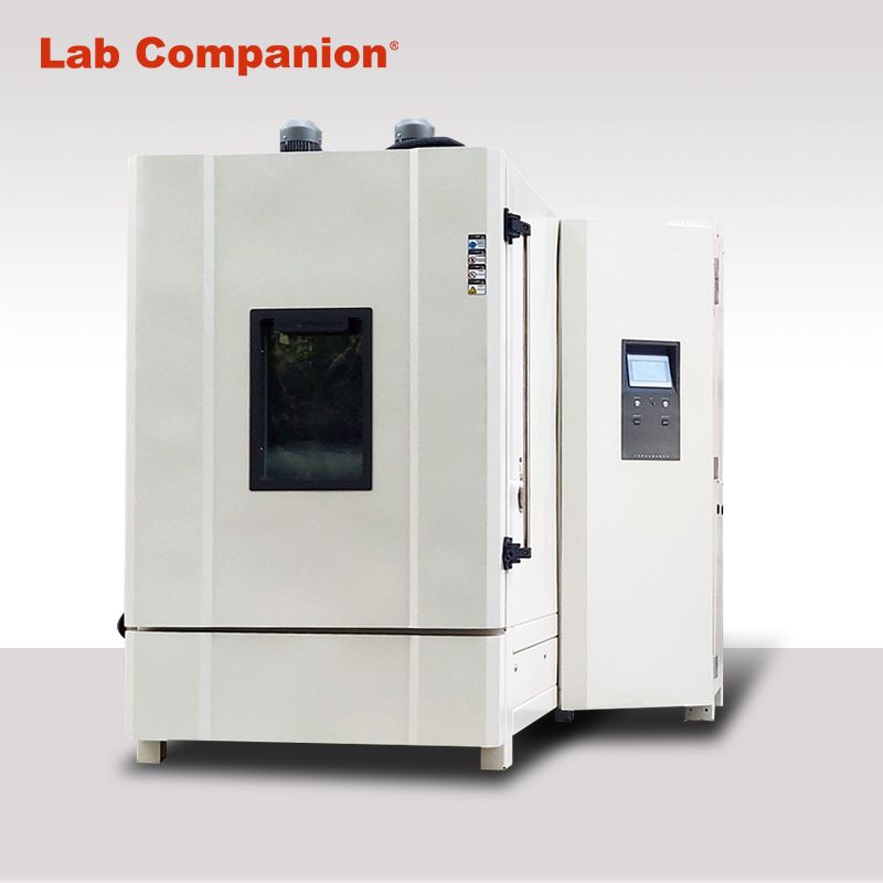
Temperature & humidity test chamber of Lab Companion
Temperature & humidity test chamber series, passed the CE certification, offer 34L, 64L, 100L, 180L, 340L, 600L, 1000L, 1500L and other volume models to meet the needs of different customers. In design, they use environment-friendly refrigerant and high-performance refrigeration system, parts and components are used in the international famous brand.
Heat Pipe Reliability Test
Heat pipe technology is a heat transfer element called "heat pipe" invented by G.M. rover of Los Alamos National Laboratory in 1963, which makes full use of the principle of heat conduction and the rapid heat transfer properties of the refrigeration medium, and transfers the heat of the heating object quickly to the heat source through the heat pipe. Its thermal conductivity exceeds that of any known metal. Heat pipe technology has been widely used in aerospace, military and other industries, since it has been introduced into the radiator manufacturing industry, making people change the design idea of the traditional radiator, and get rid of the single heat dissipation mode that simply relies on high air volume motor to obtain better heat dissipation effect. The use of heat pipe technology makes the radiator even if the use of low speed, low air volume motor, can also get satisfactory results, so that the noise problem plagued by air cooling heat has been well solved, opening up a new world in the heat dissipation industry.
Heat pipe reliability test conditions:
High temperature stress screening test: 150℃/24 hours
Temperature cycling test:
120℃(10min)←→-30℃(10min), Ramp: 0.5℃, 10cycles 125℃(60min)←→-40℃(60min), Ramp: 2.75℃, 10cycles
Thermal shock test:
120℃(2min)←→-30℃(2min), 250 cycles
125℃(5min)←→-40℃(5min), 250 cycles
100℃(5min)←→-50℃(5min), 2000 cycles(check once after 200 cycles)
High temperature and high humidity test:
85℃/85%R.H./1000 hours
Accelerated aging test:
110℃/85%RH/264h
Other heat pipe test items:
Salt spray test, strength (blasting) test, leakage rate test, vibration test, random vibration test, mechanical shock test, helium combustion test, performance test, wind tunnel test
Multi-touch Panel Testing
When the human body is close to the touchpad, the capacitance value between the sensing pad and the ground will change (general pf level). Capacitive touch pad (also known as: Surface capacitive) is through the use of the sensor detected by the change of capacitance value by calculating microprocessor, filtering interference and finally determining whether there is a human body close to achieve the key function. Compared with the traditional mechanical keys, the advantage is that there is no mechanical damage, and non-metals such as glass, acrylic, plastic can be used as the operating panel isolation, making the appearance of the product more atmospheric. In contrast, it can also realize the sliding operation that is difficult to achieve with traditional mechanical keys, so that the human-machine interface is more in line with the intuitive operation of people.
The outermost layer of the capacitive touch panel is a thin silicon dioxide hardening processing layer, and its hardness reaches 7; The second layer is ITO(conductive coating), through the conductive layer on the front of the average distribution of low-voltage conduction current, to establish a uniform electric field on the glass surface, when the finger touches the surface of the touch panel, it will absorb a small amount of current from the contact point, resulting in a voltage drop of the corner electrode, the use of sensing the weak current of the human body to achieve the purpose of touch; The function of the bottom layer of ITO is to shield electromagnetic waves, so that the touch panel can work in a good environment without interference. While the projective capacitive, which is the touch mode used by the famous Apple iPhone and Windows 7, has the feature of supporting multi-touch, which can shorten the user's learning time, just use the finger belly touch panel to avoid the use of stylus, and has higher light transmission and more power saving, more scratch resistance than resistive type (hardness up to 7H or more), greatly increase the service life without correction...
Touch technology can be divided into four kinds according to the principle of sensing, including resistive, capacitive, surface acoustic wave and optics. And capacitive can also be divided into surface capacitive and projected capacitive two kinds.
Touch technology applications:
Industrial applications (automatic processing machines, measuring instruments, centralized monitoring and control)
Commercial applications (ticketing systems, POS, ATMs, vending machines, stored value machines)
Life applications (cell phones, satellite positioning GPS, UMPC, small laptop)
Education and entertainment (e-books, portable game consoles, jukeboxes, electronic dictionaries)
Comparison of touch panel light transmission rate: resistive (85%), capacitive (93%)
Multi-touch panel test conditions:
Operating temperature range: -20℃~70℃/20%~85%RH
Storage temperature range: -50℃~85℃/10%~90%RH
High temperature test: 70℃/240, 500 hours, 80℃/240, 1000 hours, 85℃/1000 hours, 100℃/240 hours
Low temperature test: -20℃/240 hours, -40℃/240, 500 hours, -40℃/1000 hours
High temperature and high humidity test: 60℃/90%RH/240hours, 60℃/95%RH/1000hours 70℃/80%RH/500hours, 70℃/90%RH/240,500,1000hours, 70℃/95%RH/500hours 85℃/85%RH/1000hours, 85℃/90%RH/1000hours
Boiling test: 100℃/100%RH/100 minutes
Temperature shock - high and low temperature: (Temperature shock test is not equivalent to temperature cycling test )
-30℃←→80℃, 500cycles
-40℃(30min)←→70(30min)℃, 10cycles
-40℃←→70℃, 50, 100cycles
-40℃(30min)←→110℃(30min), 100cycles
-40℃(30min)←→80℃(30min), 10, 100cycles
-40℃(30min)←→90℃(30min), 100cycles
Thermal Shock Test - Liquid Type: -40℃←→90℃, 2cycles
Cold and thermal shock test-over room temperature: -30℃(30min)→R.T. (5min)→80℃(30min), 20cycles
Service life: 1,000,000 times, 2,000,000 times, 35,000,000 times, 225,000,000 times, 300,000,000 times
Hardness test: greater than hardness level 7 (ASTM D 3363, JIS 5400)
Impact Test: With more than 5kg of force, strike the panel on the most vulnerable area and the center of the panel respectively.
Pin(Tail) Pulling Test: 5 or 10kg downward pulling.
Pin Folding Test:135¢angle, left and right back and forth for 10 times.
Impact resistance test: 11φ/5.5g copper ball dropped at 1.8m height on the center surface of 1m object, 3ψ/9g stainless steel ball dropped at 30cm height.
Writing durability: 100,000 characters or more (width R0.8mm, pressure 250g)
Touch durability: 1,000,000, 10,000,000, 160,000,000, 200,000,000 times or more (width R8 mm, hardness 60°, pressure 250g, 2 times per second)
Test equipment:
Test equipment
Test Requirements and Conditions
Temperature & humidity test chamber
Equipment features: high-strength, high-reliability structural design - to ensure the high reliability of the equipment; working room materials for the SUS304 stainless steel - corrosion resistance, strong anti-fatigue thermal function, long service life; high-density polyurethane foam insulation materials - to ensure that the heat loss is reduced to a little; the surface of the plastic spraying treatment - to ensure that the equipment's lasting corrosion-resistant function and the appearance of the life; high-strength temperature-resistant Silicone rubber sealing strip - to ensure the high sealing of the equipment door.
High temperature & high humidity test chamber
High temperature and high humidity test chamber series, passed the CE certification, offer 34L, 64L, 100L, 180L, 340L, 600L, 1000L, 1500L and other volume models to meet the needs of different customers. In design, they use environment-friendly refrigerant and high-performance refrigeration system, parts and components are used in the international famous brand.
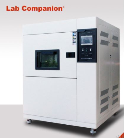
Two-Zone(Basket Type)
Thermal shock test chamber
Applicable to the assessment of products (the whole machine), parts and components, etc. to withstand rapid changes in temperature. Thermal shock test chambers can understand the impact of the test sample once or repeatedly due to temperature changes. The main parameters affecting the temperature change test are the high and low temperature values of the temperature change range, the retention time of the sample at high and low temperature, and the number of test cycles.
Three-zone (Ventilation Type)
Thermal shock test chamber
TS series thermal shock test chambers have complete equipment specifications - two-zone(basket type), three-zone (ventilation type) and horizontal movement type are available for users to choose, fully meeting the various requirements of different users; The equipment can also provide standard high and low temperature test function to achieve the compatibility of temperature shock and high and low temperature test; high strength, high reliability of the structure design - ensure the high reliability of the equipment.
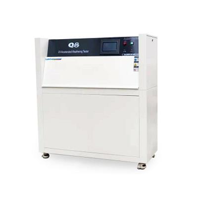
UV aging tester testing equipment
The structure of the test chamber is made of corrosion-resistant metal materials, including 8 fluorescent ultraviolet lamps, a water tray, a test sample holder, and temperature and time control systems and indicators.
2. The lamp power is 40W and the lamp length is 1200mm. The range of the uniform working area of the test box is 900 × 210mm.
3. The lights are installed in four rows, divided into two rows. The tubes of each row of lights are installed in parallel, and the center distance of the lights is 70mm.
4. The test sample is fixedly installed at a position 50mm away from the surface of the lamp surface. The test sample and its bracket form the inner wall of the box, and their backs are exposed to cooling air at room temperature due to the temperature difference between the test sample and the air inside the box. To create stable condensation conditions on the surface of the test sample during the condensation stage, the test chamber should generate natural air convection through the outer wall of the chamber and the channel of the test sample at the bottom.
5. Water vapor is generated by a water tray located at the bottom of the heating box, with a water depth not exceeding 25mm, and equipped with an automatic water supply controller. The water tray should be regularly cleaned to prevent the formation of scale.
6. The temperature of the test chamber is measured by a sensor fixed on a black aluminum plate (blackboard) with a width of 75mm, height of 100mm, and thickness of 2.5mm. The blackboard should be placed in the central area of the exposure test, and the measurement range of the thermometer is 30-80 ℃ with a tolerance of ± 1 ℃. The control of lighting and condensation stages should be carried out separately, and the condensation stage is controlled by the heating water temperature.
7. The test chamber should be placed in a test room with a temperature of 15-35 ℃, 300mm away from the wall, and should prevent the influence of other heat sources. The air in the test room should not circulate strongly to avoid affecting the lighting and condensation conditions.
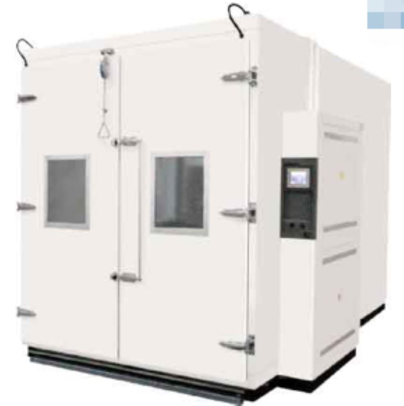
Dear customer:
Hello, our company is a high-quality development team with strong technical strength, providing high-quality products, complete solutions, and excellent technical services to our customers. The main products include walk-in constant temperature and humidity testing chambers, UV accelerated aging testing machines, rapid temperature change testing chambers, walk-in environmental testing chambers, UV aging testers, constant temperature and humidity chambers, etc. Our company adheres to the principle of building a business with integrity, maintaining quality, and striving for progress. With a more determined pace, we continuously climb new heights and contribute to the national automation industry. We welcome new and old customers to confidently choose the products they like. We will serve you wholeheartedly!
Bicycle Lamp Reliability Test
Bicycles are in the social environment of high oil prices and environmental protection, with environmental protection, fitness, slow living... Such as multi-functional recreational sports equipment, and bicycle lights are an indispensable and important part of bicycle night riding, if the purchase of low-cost and not after reliability test of bicycle lights, riding at night or through the tunnel failure, not only for the rider has a serious threat to life safety, For driving, collision accidents can occur because the driver cannot see the cyclist, so it is important to have bicycle lights that pass the reliability test.
Reasons for bicycle lamp failure:
a. Deformation, embrittlement and fading of lamp shell caused by high temperature of lamp
b. yellowing and embrittlement of lamp shell caused by outdoor ultraviolet exposure
c. Riding up and down the hill due to high and low temperature changes in the environment caused by lamp failure
d. Abnormal power consumption of car lights
e. Lights fail after a long time of rain
f. Hot failure occurs when the lights are lit for a long time
g. During riding, the lamp fixture drags loose, causing the lamp to fall
h. Lamp circuit failure caused by road vibration and slope
Bicycle lamp test classification:
Environmental test, mechanical test, radiation test, electrical test
Initial characteristic test:
Take any 30, light the lamp with DC power supply according to the rated voltage, after the characteristics are stable, measure the distance between the current and the optical center, less than 10 defective products are qualified, more than 22 are unqualified, if the number of defective products is between 11 and 22, another 100 samples are collected for testing, and the number of defective products under the original inspection is qualified when the number is less than 22. If the number exceeds 22, it is disqualified.
Life test: 10 bulbs passed the initial characteristic test, and 8 of them met the requirements.
Bicycle test speed: simulated 15 km/h environment
High temperature test (temperature test) : 80℃, 85℃, 90℃
Low temperature test: -20℃
Temperature cycle: 50℃(60min)→ normal temperature (30min)→20(60min)→ normal temperature (30min), 2cycle
Wet heat test: 30℃/95%R.H/48 hours
Stress screening test: High temperature: 85℃←→ Low temperature: -25℃, dwell time: 30min, cycle: 5cycles, power on, time: ≧24h
Shell salt spray test: 20℃/15% salt concentration/spray for 6 hours, determination method: the surface of the shell should not occur obvious rust
Waterproof test:
Description: The IPX rating of rainproof lamps needs to be at least IPX3 or above
IPX3(Water resistance) : Drop 10 liters of water vertically from a height of 200CM at 60˚ (test time: 10 minutes)
IPX4(anti-water, anti-splash) : 10 liters of water drops from 30 ~ 50CM in any direction (test time: 10 minutes)
IPX5:3m 12.5L of water from any direction [weak water](test time: 3 minutes)
IPX6:3m Strong spray 30 liters from any direction [strong water, pressure: 100KPa](test time: 3 minutes)
IPX7(Life waterproof) : It can be used for 30 minutes under 1m in water
Vibration test: vibration number 11.7 ~ 20Hz/amplitude: 11 ~ 4mm/ time: up and down 2h, about 2h, 2h before and after 2h/acceleration 4 ~ 5g
Drop test: 1 meter (hand drop), 2 meters (bicycle fall, fall from the frame)/ concrete floor/four times/four sides
Impact test: 10mm flat wooden platform/Distance: 1 m/diameter 20mm mass 36g steel ball free fall/top surface and side once
Low temperature impact: When the sample is cold to -5℃, maintain this temperature for three hours and then carry out the impact test
Irradiation test: long time irradiation brightness test, low voltage irradiation test, light brightness, light color
Bicycle lamp noun sorting:
Natural Convection Test (No Wind Circulation Temperature Test) and Specification
Home entertainment audio-visual equipment and automotive electronics are one of the key products of many manufacturers, and the product in the development process must simulate the adaptability of the product to temperature and electronic characteristics at different temperatures. However, when the general oven or constant temperature and humidity test chamber is used to simulate the temperature environment, both the oven and constant temperature and humidity test chamber have a test area equipped with a circulating fan, so there will be wind speed problems in the test area. During the test, the temperature uniformity is balanced by rotating the circulating fan. Although the temperature uniformity of the test area can be achieved through the wind circulation, the heat of the product to be tested will also be taken away by the circulating air, which will be significantly inconsistent with the actual product in the wind-free use environment (such as the living room, indoor). Because of the relationship of wind circulation, the temperature difference of the product to be tested will be nearly 10 ° C, in order to simulate the actual use of environmental conditions, many people will misunderstand that only the test machine can produce temperature (such as: oven, constant temperature and humidity test chamber) can carry out natural convection test, in fact, this is not the case. In the specification, there are special requirements for wind speed, and a test environment without wind speed is required. Through the natural convection test equipment (no forced wind circulation test), the temperature environment without fan is generated (natural convection test), and then the test integration test is carried out to detect the temperature of the product under test. This solution can be applied to the actual ambient temperature test of household related electronic products or confined Spaces (such as: Large LCD TV, car cockpit, car electronics, laptop, desktop computer, game console, stereo... Etc.).
The difference of the test environment with or without wind circulation for the test of the product to be tested:
If the product to be tested is not energized, the product to be tested will not heat itself, its heat source only absorbs the air heat in the test furnace, and if the product to be tested is energized and heated, the wind circulation in the test furnace will take away the heat of the product to be tested. Every 1 meter increase in wind speed, its heat will be reduced by about 10%. Suppose to simulate the temperature characteristics of electronic products in an indoor environment without air conditioning, if an oven or a constant temperature and humidity test chamber is used to simulate 35 ° C, although the environment in the test area can be controlled within 35 ° C through electric heating and freezing, the wind circulation of the oven and the constant temperature and humidity test chamber will take away the heat of the product to be tested, making the actual temperature of the product to be tested lower than the temperature in the real state of no wind. Therefore, it is necessary to use a natural convection testing machine without wind speed to effectively simulate the actual windless environment (such as: indoor, non-starting car cockpit, instrument chassis, outdoor waterproof box... Such environment).
Indoor environment without wind circulation and solar radiant heat irradiation:
Through the natural convection tester, simulate the client's actual use of the real air conditioning convection environment, hot spot analysis and heat dissipation characteristics of the product evaluation, such as the LCD TV in the photo not only to consider its own heat dissipation, but also to evaluate the impact of thermal radiation outside the window, thermal radiation for the product may produce additional radiant heat above 35 ° C.
Comparison table of wind speed and IC product to be tested:
When the ambient wind speed is faster, the IC surface temperature will also take away the IC surface heat due to the wind cycle, resulting in faster wind speed and lower temperature, when the wind speed is 0, the temperature is 100℃, but when the wind speed reaches 5m/s, the IC surface temperature has been below 80℃.
Unforced air circulation test:
According to the specification requirements of IEC60068-2-2, in the high temperature test process, it is necessary to carry out the test conditions without forced air circulation, the test process needs to be maintained under the wind-free circulation component, and the high temperature test is carried out in the test furnace, so the test cannot be carried out through the constant temperature and humidity test chamber or oven, and the natural convection tester can be used to simulate the free air conditions.
Description of test conditions:
Test specification for unforced air circulation: IEC-68-2-2, GB2423.2, GB2423.2-89 3.3.1
Unforced air circulation test: The test condition of unforced air circulation can simulate the free air condition well
GB2423.2-89 3.1.1:
When measuring under free air conditions, when the temperature of the test sample is stable, the temperature of the most hot spot on the surface is more than 5℃ higher than the temperature of the surrounding large device, it is a heat dissipation test sample, otherwise it is a non-heat dissipation test sample.
GB2423.2-8 10(Test heat dissipation test sample temperature gradient test) :
A standard test procedure is provided to determine the adaptability of thermal electronic products (including components, equipment level other products) to use at high temperatures.
Test requirements:
a. Testing machine without forced air circulation (equipped with a fan or blower)
b. Single test sample
c. The heating rate is not greater than 1℃/min
d. After the temperature of the test sample reaches stability, the test sample is energized or the home electrical load is carried out to detect the electrical performance
Natural convection test chamber features:
1. Can evaluate the heat output of the product to be tested after power, to provide the best distribution uniformity;
2. Combined with digital data collector, effectively measure the relevant temperature information of the product to be tested for synchronous multi-track analysis;
3. Record the information of more than 20 rails (synchronous record the temperature distribution inside the test furnace, multi-track temperature of the product to be tested, average temperature... Etc.).
4. The controller can directly display the multi-track temperature record value and record curve; Multi-track test curves can be stored on a USB drive via the controller;
5. The curve analysis software can intuitively display the multi-track temperature curve and output EXCEL reports, and the controller has three kinds of display [Complex English];
6. Multi-type thermocouple temperature sensor selection (B, E, J, K, N, R, S, T);
7. Scalable to increase heating rate & control stability planning.
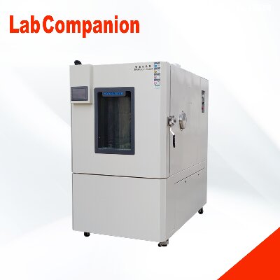
Structural characteristics of temperature and humidity control box
The full name of the temperature and humidity control chamber is "Constant Temperature and Humidity Test Chamber", which is an essential testing equipment in aviation, automotive, home appliances, scientific research and other fields. It is used to test and determine the parameters and performance of electrical, electronic and other products and materials after high temperature, low temperature, humidity and heat or constant temperature environment changes. It can be mainly divided into "desktop" and "vertical" according to testing requirements and standards, with the difference being the temperature and humidity that can be achieved. The vertical type can be used for low temperature and drying below room temperature, while the desktop type can only be used for temperature and high humidity above room temperature.
Suitable for various small electrical appliances, instruments, materials, and components for wet heat testing, it is also suitable for conducting aging tests. This test chamber adopts the most reasonable structure and stable and reliable control method currently available, making it aesthetically pleasing, easy to operate, safe, and with high precision in temperature and humidity control. It is an ideal equipment for conducting constant temperature and humidity tests.
1) The test box body is in the form of an integral structure, with the refrigeration system located at the lower rear of the box and the control system located at the upper part of the test box.
(2) Inside the air duct interlayer at one end of the studio, there are devices such as heaters, refrigeration evaporators, and fan blades distributed; On the left side of the test box, there is a Ø 50 cable hole, and the test box is a single door (stainless steel embedded door handle)
(3) The double-layer high temperature and anti-aging silicone rubber seal can effectively ensure the temperature loss of the test chamber
(4) There are observation windows, frost prevention devices, and switchable lighting fixtures on the box door. The observation window adopts multi-layer hollow tempered glass, and the inner adhesive sheet conductive film is heated and defrosted. The lighting fixtures use imported brand Philips lamps, which can effectively observe the experimental changes in the studio from all angles.
Dear customer:
Hello, our company is a high-quality development team with strong technical strength, providing high-quality products, complete solutions, and excellent technical services to our customers. The main products include walk-in constant temperature and humidity testing chambers, UV accelerated aging testing machines, rapid temperature change testing chambers, walk-in environmental testing chambers, UV aging testers, constant temperature and humidity chambers, etc. Our company adheres to the principle of building a business with integrity, maintaining quality, and striving for progress. With a more determined pace, we continuously climb new heights and contribute to the national automation industry. We welcome new and old customers to confidently choose the products they like. We will serve you wholeheartedly!


 Get A Quote


 IPv6 network supported