Lab Industrial High-Temperature Aging Oven
Nov 05, 2025
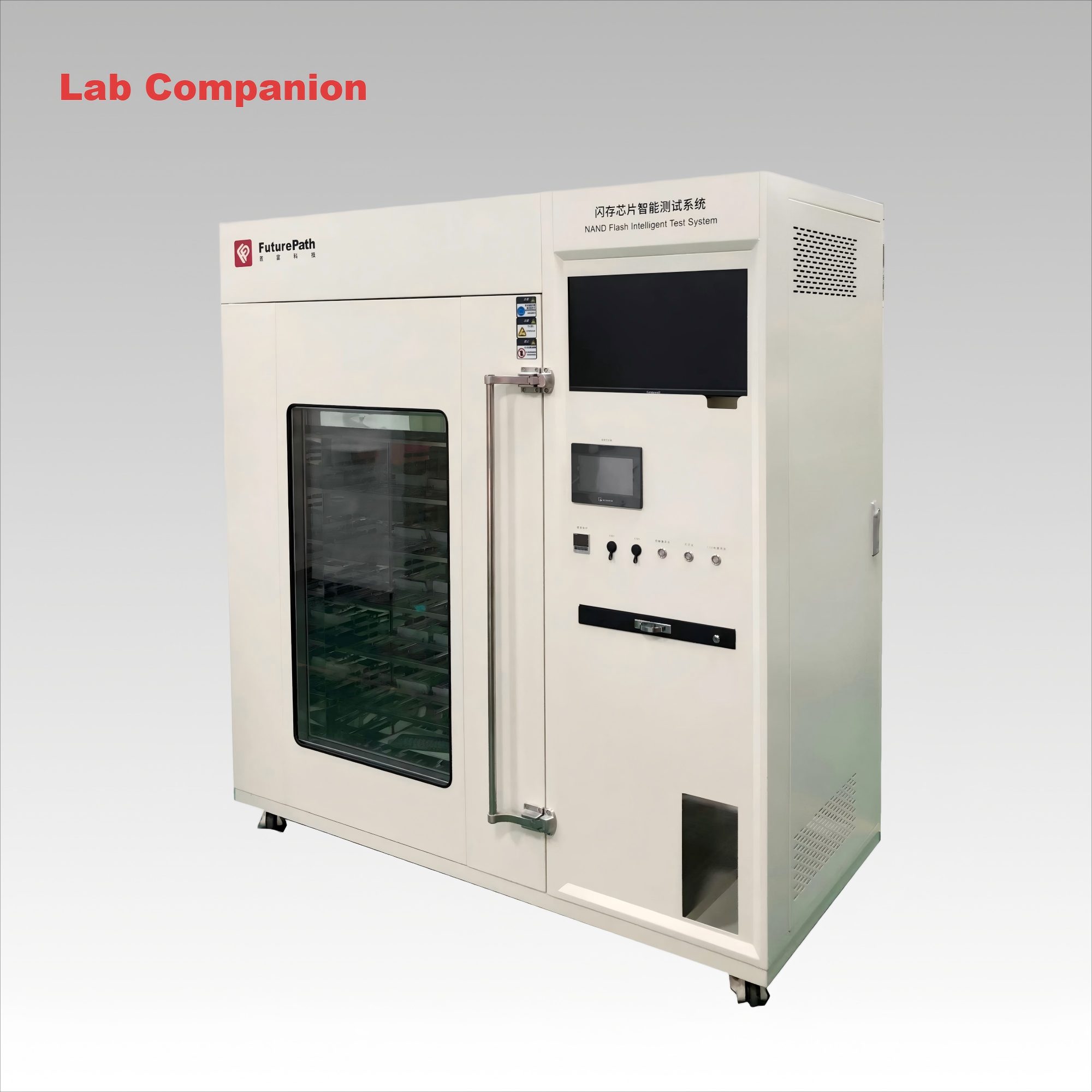
An industrial high-temperature aging oven is a device that conducts accelerated aging tests on industrial products (such as electronics, electrical appliances, components, chemical materials, etc.) by simulating high-temperature environments. By applying high-temperature stress, potential defects and faults of the products can be exposed in advance, thereby screening out early-failed products and enhancing the reliability and stability of the products leaving the factory. Its core components mainly include the heating system, circulation system, control system and safety protection system.
Main features: Firstly, it has a wide operating temperature range, typically from room temperature +10°C to +200°C or 300 °C. Temperature uniformity is a key indicator for evaluating the performance of an oven. The temperature difference at each point inside the oven is ±2°C, and the temperature control accuracy usually reaches ±0.1°C to ±1°C, ensuring the precision and repeatability of the test conditions. In addition, the heating rate can be set according to the test requirements, ranging from linear heating to rapid heating. The internal structure of the test chamber is usually made of stainless steel (such as SUS304), which is heat-resistant and corrosion-resistant. The shell is generally made of high-quality cold-rolled steel plate and the surface is treated with plastic spraying. Finally, the insulation layer is usually made of high-density aluminosilicate cotton or rock wool, with sufficient thickness to ensure that the surface temperature of the box is low and energy-saving. The air duct is designed for horizontal or vertical air supply to ensure that the hot air can flow evenly through each product under test.
Aging ovens are widely used in all industries that have high requirements for product reliability:
Electronics industry: IC chips, PCB circuit boards, power supplies, chargers, LED displays/lamps, automotive electronics, etc.
Electric appliances: transformers, relays, capacitors, circuit breakers, motors, etc.
Communication products: mobile phones, routers, base station equipment, optical modules, etc.
Chemical materials: Conduct high-temperature aging resistance tests on coatings, plastics, rubbers, adhesives, etc.
Automotive parts: various sensors, controllers (ECUs), wiring harnesses, etc.
How to choose the right industrial high-temperature aging oven? When making a choice, the following factors need to be comprehensively considered:
1. Temperature range: According to the product testing standards, select the model that can meet the highest and lowest temperature requirements, and leave a certain margin.
2. Inner box size: Select an appropriate volume based on the size and quantity of the products to be tested. Remember to reserve space to ensure air circulation.
3. Temperature uniformity and accuracy: The higher the requirements, the higher the equipment cost and manufacturing difficulty. Choose according to the strictness of the test.
4. Load condition: If the product will generate heat by itself during the testing process (i.e., "load testing"), it is necessary to inform the equipment manufacturer so that they can calculate and configure sufficient heating and heat dissipation capacity.
5. Control System and Functions:
Is program control (multi-stage temperature rise and heat preservation) required?
Is it necessary to record and export the temperature curve data?
Whether remote monitoring and other factors are needed
Industrial high-temperature aging ovens are an indispensable part of modern quality engineering. Through sample aging tests, it intercepts potential faulty products before they leave the factory, significantly reducing the market return rate and after-sales maintenance costs, and earning credibility and long-term benefits for the enterprise. When making a purchase, you can communicate fully with us based on the characteristics of your own products and testing requirements, and choose the most suitable solution.
Read More


 Get A Quote


 IPv6 network supported